Transcript for Setting The Work Table Level
1
00:00:06,440 –> 00:00:16,490
The Concise RDWorks Learning Lab with Russ Sadler. Session 15: Setting The Work Table Level.
2
00:00:16,490 –> 00:00:22,910
I’m nice and clean at the moment, but in today’s session, I think we’re going to get maybe a little bit grubby.
3
00:00:22,910 –> 00:00:26,930
We’re going to look at this thing here, the work table.
4
00:00:26,930 –> 00:00:31,760
It’s an essential part of setting this machine before you really start using it,
5
00:00:31,760 –> 00:00:38,440
that you set the table up level. Level implies maybe using one of these things.
6
00:00:38,440 –> 00:00:44,440
No, forget that. That’s not what we’re talking about when we talk about level, your machine can be totally on the wonk.
7
00:00:44,440 –> 00:00:52,930
It isn’t a problem. What we’re really interested in doing, setting the table, absolutely true to the bearing rails.
8
00:00:52,930 –> 00:00:57,850
In other words, we want this to be flat in this plane running true to that bearing
9
00:00:57,850 –> 00:01:05,500
rail. And we want it in this plane running true to the Y bearing rails.
10
00:01:05,500 –> 00:01:11,260
Before we do that, I think I really ought to explain why we need it. Now,
11
00:01:11,260 –> 00:01:18,160
one of the most complicated and misunderstood things about this machine, are these things, lenses.
12
00:01:18,160 –> 00:01:25,360
I’m not going to get into a rant of mine about lenses because that’s something that
13
00:01:25,360 –> 00:01:30,490
I’m afraid you’re going to have to suffer in the future. For four or five years,
14
00:01:30,490 –> 00:01:34,990
I was very happy with standard lens theory.
15
00:01:34,990 –> 00:01:42,580
And I’m going to go through this very briefly just to explain why we need the machines set up level.
16
00:01:42,580 –> 00:01:52,440
The uses of lenses and light, even though this is an invisible light source, is well described by standard lens theory.
17
00:01:52,440 –> 00:02:01,230
But standard lens theory is all about images, microscopes, telescopes, cameras, projectors.
Transcript for Setting The Work Table Level
18
00:02:01,230 –> 00:02:07,890
It’s not really about laser beams. Let’s just look to see what standard lens theory tells us about lenses.
19
00:02:07,890 –> 00:02:10,830
We’ve got different focal length lenses.
20
00:02:10,830 –> 00:02:20,340
Now, here’s a typical example from a company, a Chinese lens company, which explains in very simple pictorial forms what’s going on.
21
00:02:20,340 –> 00:02:24,690
We’ve got four inch lens, a two and a half inch lens, a two inch and a one and a half inch lens.
22
00:02:24,690 –> 00:02:30,420
Forget this thing on the end. OK, so they’re the lenses that you’re most likely to come across.
23
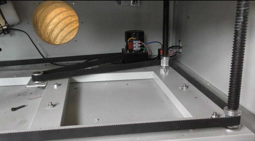
00:02:30,420 –> 00:02:38,550
And basically there are two pieces of information which are stated about a lens, apart from the focal length.
24
00:02:38,550 –> 00:02:47,850
One of them is the so-called spot size, which is the point through which all the rays of light pass.
25
00:02:47,850 –> 00:02:52,800
Now, the longer the focal length of the lens, the bigger the cut width,
26
00:02:52,800 –> 00:02:59,400
because the bigger the spot size or the beam diameter that you’re going to get at the focal point.
27
00:02:59,400 –> 00:03:03,600
The width of the cut you should be able to achieve with these lenses.
28
00:03:03,600 –> 00:03:08,250
The second piece of information is this little square here.
29
00:03:08,250 –> 00:03:15,210
Now, this little square here defines what they call the working depth of the lens.
30
00:03:15,210 –> 00:03:21,750
Now there’s another company around called Parallax Technology, which you might like to go and look at their website because they have got a very
31
00:03:21,750 –> 00:03:27,740
understandable section about lenses and how lenses work and the various things.
32
00:03:27,740 –> 00:03:32,310
This is all standard lens theory without any really complicated formulas.
33
00:03:32,310 –> 00:03:36,150
It just describes very nicely how lenses work.
34
00:03:36,150 –> 00:03:45,930
And when we look at their charts in here, what we find is that they’ve defined, again, the spot size in millimeters and in inches.
35
00:03:45,930 –> 00:03:50,990
And they’ve also giving you this thing depth of field, which is the point that I was talking about. Here’s,
36
00:03:50,990 –> 00:03:58,720
here’s the focal point where all the rays pass through one single point and then either side of that,
Transcript for Setting The Work Table Level
37
00:03:58,720 –> 00:04:05,820
you’ve got this depth of field, as they call it. Now, the depth of field is plus or minus these numbers.
38
00:04:05,820 –> 00:04:09,990
So whatever the spot size is, multiply it by one point four.
39
00:04:09,990 –> 00:04:20,610
And when we get out to that distance, that’s when we’ve got roughly half the energy density that we had at the focal point itself.
40
00:04:20,610 –> 00:04:24,720
Now, what’s energy density? This is again a very controversial subject,
41
00:04:24,720 –> 00:04:33,540
because if I put 60 Watts into an area and let’s call it an area of one, it doesn’t matter what the area is.
42
00:04:33,540 –> 00:04:45,330
That means I’ve got 60 watts per unit area. Well, if I go out to one point four, I’ve doubled the area and I will finish up with half the energy density.
43
00:04:45,330 –> 00:04:52,560
So instead of 60 watts per unit area at this point here, I’m going to finish up with 30 watts per unit area.
44
00:04:52,560 –> 00:04:59,310
That’s the way the theory runs. If we’re setting our machine up somewhere in one position and we set the focus up,
45
00:04:59,310 –> 00:05:06,360
but then we finish up somewhere else on the table and the focal point has moved to here because the table has dropped away, that’s no good to us.
46
00:05:06,360 –> 00:05:12,300
This nozzle is fixed through this lump of metal to the bearing rail.
47
00:05:12,300 –> 00:05:22,080
As I move the head backwards and forwards, it remains perfectly in line with this bearing rail and with this bearing rail.
48
00:05:22,080 –> 00:05:31,290
This nozzle represents a perfect reference because what we’re trying to do is to set the table
49
00:05:31,290 –> 00:05:37,590
so that it always remains the same distance below the nozzle because it’s below the nozzle,
50
00:05:37,590 –> 00:05:44,610
that the focal point exists and we can’t have the focal point drifting in and out of focus.
51
00:05:44,610 –> 00:05:48,750
So we want the table to be true to the end of the nozzle.
52
00:05:48,750 –> 00:05:55,320
And that is what leveling the table means. Now, when you open your machine up and look underneath the table.
53
00:05:55,320 –> 00:06:00,120
There are many things that you might find. In this instance,
Transcript for Setting The Work Table Level
54
00:06:00,120 –> 00:06:10,130
I have a stepper motor here which is driving the table up and down in a controlled manner.
55
00:06:10,130 –> 00:06:25,310
That’s what this machine does, but it does so via a toothed belt and some toothed pullys, which are driving the table up and down on a big screw thread.
56
00:06:25,310 –> 00:06:32,660
Now these screw threads are fixed relative to each other via this tool belt. As one rotates,
57
00:06:32,660 –> 00:06:38,760
so they all rotate and the table moves up and down in a nice parallel plane.
58
00:06:38,760 –> 00:06:45,410
But of course, if one of those screws is out of position, then the table is not flat.
59
00:06:45,410 –> 00:06:49,850
OK, now your machine might not look like this. It may have a cover over here,
60
00:06:49,850 –> 00:06:55,310
for example. You’ll have to take the cover off and when you take it off, you’ll find the belt.
61
00:06:55,310 –> 00:07:00,920
Some machines have got two stepper motors because it’s a big machine and they’ve got two belts.
62
00:07:00,920 –> 00:07:06,440
Now, that’s a bit of a nightmare because two stepper motors, if they get out of synchronization,
63
00:07:06,440 –> 00:07:10,160
one side of the table will be going up and down at a different height to the other side.
64
00:07:10,160 –> 00:07:14,000
Something you’ll have to keep an eye on if you have a two stepper motor system. That
65
00:07:14,000 –> 00:07:21,590
normally only applies to big machines, because you can’t get toothed belts very,
66
00:07:21,590 –> 00:07:25,910
very long. And so consequently, on some machines, you may well find that
67
00:07:25,910 –> 00:07:30,710
they don’t use tooth belts. They use a chain. That’s fine.
68
00:07:30,710 –> 00:07:37,170
A chain works just as well as a tooth belt because it keeps these screws fully synchronized.
69
00:07:37,170 –> 00:07:45,230
Now, not every system has a stepper motor on it. This machine.
70
00:07:45,230 –> 00:07:52,610
It’s completely different, but exactly the same. What we have at the back there is a DC motor, not a stepper motor,
71
00:07:52,610 –> 00:07:59,840
and I’ve got two buttons on the side of the machine that allows the motor to either drive clockwise or anticlockwise.
Transcript for Setting The Work Table Level
72
00:07:59,840 –> 00:08:04,370
It’s not stepper controlled. I’ve got no Z control on this machine.
73
00:08:04,370 –> 00:08:10,010
I’ve just got, if you like, assisted table height adjustment. But the same principle applies.
74
00:08:10,010 –> 00:08:18,650
Look, we’ve got a toothed belt. We’ve got toothed pullys and we’ve got a lead screw.
75
00:08:18,650 –> 00:08:26,030
So we shall use this machine as our example to show you how to set the table.
76
00:08:26,030 –> 00:08:33,260
OK, now it really doesn’t matter where the table is, other than the fact that it’s got to be reasonably close to the nozzle,
77
00:08:33,260 –> 00:08:37,460
because here I’ve got a little measuring gauge that I’ve made.
78
00:08:37,460 –> 00:08:42,080
This gauge is ten millimeters at this end and 12 millimeters at this end.
79
00:08:42,080 –> 00:08:46,670
And it’s divided with numbers into point one of a millimeter.
80
00:08:46,670 –> 00:08:55,590
So I’ve got a point, one of a millimeter adjustable scale here. If you use a constant amount of force till it just touches.
81
00:08:55,590 –> 00:09:03,180
It’s set to 11 millimeters. Dart to the back left hand corner, make that corner our 11 millimeter reference.
82
00:09:03,180 –> 00:09:09,770
So we’ve now got to make all other corners the same. So let’s move to the back right hand corner and check what we’ve got.
83
00:09:09,770 –> 00:09:15,930
There’s 11 mm. It’s abouta millimeter and a half out.
84
00:09:15,930 –> 00:09:19,680
Well, that is absolute rubbish. We’re going to do it on the back screw.
85
00:09:19,680 –> 00:09:30,900
But I want to show you this on that front screw. Now, we’re very lucky with this machine because the screws for fixing these are above the belt.
86
00:09:30,900 –> 00:09:33,750
On the other machine that you looked at a few seconds ago,
87
00:09:33,750 –> 00:09:41,010
fixing screws are above the belt with some, the fixing screws are actually buried in the teeth here.
88
00:09:41,010 –> 00:09:43,200
And you’ll have to hunt for them, at least with these.
89
00:09:43,200 –> 00:09:54,890
All I’ve got to do is to find the grub screws. One here and there will always be two and the other one is at ninety degrees just here.
90
00:09:54,890 –> 00:09:59,360
And then I’ll do the same with this screw at the back. Now, sadly,
Transcript for Setting The Work Table Level (Cont…)
91
00:09:59,360 –> 00:10:07,970
the screws on this back one are hidden somewhere behind here and I can’t get to it because we’ve got a micro switch bracket on the back here.
92
00:10:07,970 –> 00:10:19,820
So I haven’t got full access to that one. So what I’m going to have to do is this, bring the screws into view.
93
00:10:19,820 –> 00:10:27,110
Sounds simple enough, doesn’t it? Now I can loosen those screws and do the same to this one on the front corner here as well.
94
00:10:27,110 –> 00:10:34,670
I can access the screws here easily in any position. I can access the screws here easily in any position.
95
00:10:34,670 –> 00:10:39,050
But the screws over there in that corner are the deciding factor for me.
96
00:10:39,050 –> 00:10:46,790
Those I can only access like that. So let’s go back to the top of the table and let’s drive the head back to the starting point.
97
00:10:46,790 –> 00:10:51,980
So making that adjustment to the table height to get access to the belt has completely messed up
98
00:10:51,980 –> 00:11:02,320
our original position. Well, not really, because all we’ve got to do is undo that nozzle and let it drop down.
99
00:11:02,320 –> 00:11:11,130
And there we go, we’ve reestablished our 11 millimeter reference now. So we can now come back to this corner.
100
00:11:11,130 –> 00:11:15,040
And we shall still find we’ve got a big gap that we didn’t want.
101
00:11:15,040 –> 00:11:19,900
So what we’ve got to do now is to raise the table up in that corner.
102
00:11:19,900 –> 00:11:25,480
We did not loosen the screw in the far left hand back corner.
103
00:11:25,480 –> 00:11:27,310
So it’s not going to change.
104
00:11:27,310 –> 00:11:40,200
So the lead screw is no longer fixed to this toothed pully, so I can rotate the lead screw, as you can see, and the pully stays still.
105
00:11:40,200 –> 00:11:47,320
So all I’ve got to do now is to rotate that lead screw to get rid of the gap.
106
00:11:47,320 –> 00:11:58,880
Wrong way, it’s going to come this way. Eleven point one, little bit more.
Transcript for Setting The Work Table Level (Cont…)
107
00:11:58,880 –> 00:12:09,090
And there we go. 11 mm dead, and now Ican tighten these grub screws up nice and snug and we’ve locked that corner at 11mm
108
00:12:09,090 –> 00:12:20,580
So we now come to the front left corner of the machine and we find that it is eleven point one without touching it, it’s eleven point one.
109
00:12:20,580 –> 00:12:27,240
Do I really need to worry about point one of a millimeter? I don’t think so.
110
00:12:27,240 –> 00:12:32,220
So we shall leave that one as it is and lock the screws up.
111
00:12:32,220 –> 00:12:35,820
And the final corner is quite a long way out.
112
00:12:35,820 –> 00:12:41,640
It’s close to 12 millimeters. So that’s got to come up by a millimeter, until it touches.
113
00:12:41,640 –> 00:12:48,540
Let’s check whether or not that’s 11. It’s a bit on the snug side.
114
00:12:48,540 –> 00:13:01,010
There we go, spot on 11. So we now lock that one up as well, if we put this towards the middle of the table and it’s about eleven point one.
115
00:13:01,010 –> 00:13:08,450
So I don’t think we’re going to be too worried about that, point one of a millimeter within level all the way across the table.
116
00:13:08,450 –> 00:13:12,440
That’s pretty good. Well, my hands are not as bad as I thought they were going to be.
117
00:13:12,440 –> 00:13:19,400
So maybe I ought to put some light oil on those screw threads. They have got grease on them at the back there, if you look.
118
00:13:19,400 –> 00:13:26,690
But I think a little bit of oil would not do any harm. Now, I use this a lot around the machine.
119
00:13:26,690 –> 00:13:36,920
It’s liquid Moly, in this particular instance this is a hydraulic valve additive, but it’s a lovely, slightly sticky, thick oil.
120
00:13:36,920 –> 00:13:43,910
It really does reduce friction. So I’m going to put a little bit on here at the top where we use it most,
121
00:13:43,910 –> 00:13:49,790
and it will find its way down the threads because it’ll just work its way down the threads.
122
00:13:49,790 –> 00:13:58,490
If I put enough of it on up here. And I will just paint a little bit on the upper part of these just below the table as well.
123
00:13:58,490 –> 00:14:03,600
So that’ll be as smooth as silk. Now. And that’s it.
124
00:14:03,600 –> 00:14:12,522
Table leveling done.
Transcript for Setting The Work Table Level
 Skip to content