Skip to content
 The Concise RDWorks Learning Lab Series
Welcome to Module 2 of the new Concise RDWorks Learning Lab Series with Russ Sadler. Module 2 will build on the information learned in Module 1 and will provide practical machine set-up sessions as well as more detailed subject material. So let’s learn about implementing the Perfect laser beam alignment procedure!
In this Session, Russ looks at mirror alignment and the iteration method of beam alignment. Russ explains how and why you need to align the mirrors using this method and sorting out the 4th corner focus problem that affects some machines.
Release Date: 29th October 2021
Over the last 6 years, Russ has built up a formidable YouTube following for his RDWorks Learning Lab series which currently has over 200 videos.
The original RDWorks Learning Lab series on his “Sarbar Multimedia” YouTube Channel, follows Russ as he tries to make sense of his new Chinese laser machine and to sort out the truths, half truths and outright misleading information that is available on the web.
Six years later with over 3 million YouTube Views under his belt, Russ has become the go to resource for everything related to the Chinese CO2 laser machine user or wannabe user.

In this new series, Russ has condensed his knowledge and experience of the last 6 years to provide valuable information and insights into the purchasing, understanding, use, repair and maintenance of the Chinese CO2 laser machines and their key component parts.
Podcast Download
You can download the audio file for this video here, just click on the three dots to the right of the player:
Video Resource Files
Targets and Holder for Mk2 Head
There are no more resource files associated with this video.

External Resource Links
There are no external resource links associated with this video.
Transcript for Perfect Laser Beam Alignment Procedure
Click the “Show More” button to reveal the transcript, and use your browsers Find function to search for specific sections of interest.
1
00:00:06,440 –> 00:00:15,810
The Concise RDWorks Learning Lab with Rudd Sadler. Session 16: Perfect Laser Beam Alignment guide.
2
00:00:15,810 –> 00:00:24,990
Now today, we’re going to look at mirrors. But we already looked at mirrors in the first session.
3
00:00:24,990 –> 00:00:37,510
Yeah, we looked at the mirrors themselves and personally, it offends me when I look in the mirror because I’m not as handsome as I think I should be.
4
00:00:37,510 –> 00:00:47,020
But in this case, what we’re trying to do is we’re trying to conduct the laser beam that we spoke about last time around the machine,
5
00:00:47,020 –> 00:00:49,820
and to do that, we have to use mirrors.
6
00:00:49,820 –> 00:00:58,460
But the problem is that most people really struggle to set their mirrors to get the laser beam aligned correctly.
7
00:00:58,460 –> 00:01:07,040
Now there are hundreds of videos out there on YouTube which purport to tell you how to set your beam.
8
00:01:07,040 –> 00:01:14,720
They go through the very simple steps and procedures, but they don’t explain why you are doing it and what you’re trying to achieve.
9
00:01:14,720 –> 00:01:23,870
Now, my goal is to try and explain to you exactly how you set your beam, why you’re doing it in the way that you’re doing it.
10
00:01:23,870 –> 00:01:32,750
There are a set of logical steps that you will follow and it guarantees that you will finish up with a perfectly set laser beam.
11
00:01:32,750 –> 00:01:41,750
This is where the dodgy diagrams come in. It’s much easier to exaggerate the situation and show you what’s going on with a diagram,
12
00:01:41,750 –> 00:01:48,140
because in reality, the errors that you are going to see me talk about are very small and you might not even notice them.
13
00:01:48,140 –> 00:01:53,220
One of the important things about mirrors is the way in which they’re mounted.
14
00:01:53,220 –> 00:02:01,080
Because the way in which they’re mounted has a significant effect on the ease with which you can adjust the beam.
Transcript for Perfect Laser Beam Alignment Procedure (Cont…)
15
00:02:01,080 –> 00:02:04,110
There are basically two types of mirror holder.
16
00:02:04,110 –> 00:02:12,130
We’ve got this type here where you can see the three brass adjusting screws are set in the form of an L shape.
17
00:02:12,130 –> 00:02:17,310
And then we’ve got this weird looking arrangement here, which was on my original machine.
18
00:02:17,310 –> 00:02:21,600
I did all sorts of things to try and make this thing work.
19
00:02:21,600 –> 00:02:27,180
And it didn’t, one day it frustrated the hell out of me so much that I just ripped it off
20
00:02:27,180 –> 00:02:33,570
and replaced it with my own acrylic homemade version. With this triangular adjustment arrangement,
21
00:02:33,570 –> 00:02:37,920
you not only get X adjustment when you adjust one of these.
22
00:02:37,920 –> 00:02:41,910
You also get Z adjustment, height adjustment as well.
23
00:02:41,910 –> 00:02:54,090
With this system here, we’ve got a very simple adjustment, which is either vertical adjustment like this as we adjust that pin, which is about here.
24
00:02:54,090 –> 00:03:02,640
Or we’ve got horizontal adjustment in this plane, we adjust this screw here and we get pivoting about that plane there.
25
00:03:02,640 –> 00:03:06,240
Now we’ve gotmirror A and mirror B, I’m not going to call them one,
26
00:03:06,240 –> 00:03:12,510
two and three because these are going to change their personality as we work our way around the machine.
27
00:03:12,510 –> 00:03:18,210
Here’s our laser beam and the laser beam comes out of the tube.
28
00:03:18,210 –> 00:03:25,920
And the ideal setting for that mirror is to have the laser beam hit
29
00:03:25,920 –> 00:03:28,320
right in the center of the mirror.
30
00:03:28,320 –> 00:03:35,910
So that is the easiest mirror to set up because we’ve only got to adjust the laser beam to fire at the center of the mirror.
31
00:03:35,910 –> 00:03:49,380
Now, it does not matter whether the laser beam is like this or like this or like this or like that. Provided it strikes the middle of the mirror,
32
00:03:49,380 –> 00:04:02,280
the mirror has got full 360 degree tilt on it, so that you can adjust the error of the laser beam out before it runs down this axis here.
Transcript for Perfect Laser Beam Alignment Procedure (Cont…)
33
00:04:02,280 –> 00:04:06,960
That’s the whole point of having the mirror completely adjustable and flexible.
34
00:04:06,960 –> 00:04:12,440
The very first thing you should do is to wind these locking screws back, because to be honest.
35
00:04:12,440 –> 00:04:18,350
They’re just nothing but a pain. People spend a great deal of time messing around with these locking screws,
36
00:04:18,350 –> 00:04:23,930
thinking that locking them up is going to make their beam last and be stable forever.
37
00:04:23,930 –> 00:04:30,080
Well, yeah, it would. But the problem is, as soon as you lock up, you adjust the mirror.
38
00:04:30,080 –> 00:04:39,450
These springs on the back here are automatically clamping this and acting like an anti vibration system.
39
00:04:39,450 –> 00:04:42,690
So you don’t need these locking screws.
40
00:04:42,690 –> 00:04:52,860
So what I suggest you do before you even start, is to run around your mirror and set something like a two millimeter gap everywhere.
41
00:04:52,860 –> 00:05:00,080
Right on each corner and you can see that that’s not true there, so you can adjust that until it looks about level.
42
00:05:00,080 –> 00:05:04,310
The only reason I’m saying two millimeters is because you want to float on your mirror.
43
00:05:04,310 –> 00:05:10,090
Now, the only thing that I will point out to you is: do not
44
00:05:10,090 –> 00:05:18,040
adjust that corner one. Regard this like a door. Here, we’ve got two pivot points, two hinges.
45
00:05:18,040 –> 00:05:25,920
If we adjust this one, it’s going to make the mirror adjust in this plane about these two pivot points here.
46
00:05:25,920 –> 00:05:34,560
Equally well, when you want to adjust the beam up and down. They become the pivot points and you’re only going to adjust this one,
47
00:05:34,560 –> 00:05:40,410
so there are no circumstances existing, that really means you need to adjust this one.
48
00:05:40,410 –> 00:05:45,750
Well, depending on how that beam approaches that mirror, you’ve got to compensate for it.
49
00:05:45,750 –> 00:05:51,900
Because what we’re really trying to achieve, we’re trying to achieve that laser beam running
50
00:05:51,900 –> 00:06:03,660
absolutely true to this bearing rail in both the vertical plane when you look down upon it and in the horizontal plane when you look at it sideways.
Transcript for Perfect Laser Beam Alignment Procedure (Cont…)
51
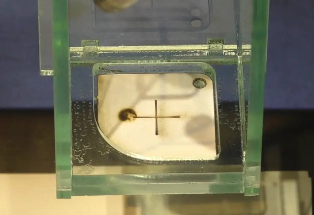
00:06:03,660 –> 00:06:10,350
So we’ve got to set that up so that this beam is adjusted in this direction and this direction,
52
00:06:10,350 –> 00:06:18,090
to hit the center of this mirror here. Instead of on center I’mre going to set it off center here.
53
00:06:18,090 –> 00:06:27,800
Now, this is not the right place for it, but this is going to show you the mechanism by which we’re going to adjust the whole system.
54
00:06:27,800 –> 00:06:33,450
OK, now, just because I’ve moved it off the center doesn’t mean I’ve changed anything.
55
00:06:33,450 –> 00:06:36,700
This is still going to perform in the same way.
56
00:06:36,700 –> 00:06:39,840
So the laser beam starts off there.
57
00:06:39,840 –> 00:06:47,880
And the first adjustment that we’re going to make is to this mirror so that we can swing that mirror and get the beam onto center.
58
00:06:47,880 –> 00:06:51,570
I’ve got a special adjustable mirror B here.
59
00:06:51,570 –> 00:06:56,610
So we move this mirror as close as possible as we can to the mirror A.
60
00:06:56,610 –> 00:07:00,240
I am purposely marking this so that we can line it all up again.
61
00:07:00,240 –> 00:07:03,930
We’ve got a red mark on here on the center and we’ve got our X there.
62
00:07:03,930 –> 00:07:13,200
The first thing I must show you is that, look, we’ve moved this mirror and I purposely made it so that it runs along this bearing rail here.
63
00:07:13,200 –> 00:07:19,320
Look at the position of the red mark. So we bring these two mirrors as close as we can together.
64
00:07:19,320 –> 00:07:30,600
We put some tape on the mirror, obviously. So that we can record where the laser beam is hitting and the laser beam is hitting just here.
65
00:07:30,600 –> 00:07:41,080
When we move back to its original position here, remember here, the blue mark, is a certain distance away from this rail.
66
00:07:41,080 –> 00:07:45,460
Down here, it’s exactly the same distance away from the rail,
67
00:07:45,460 –> 00:07:51,700
and so ideally any line that struck through these blue lines is going to be what we want.
68
00:07:51,700 –> 00:08:01,890
It’s parallel to this bearing rail. OK, so let’s do that now, let’s now adjust this mirror,
Transcript for Perfect Laser Beam Alignment Procedure (Cont…)
69
00:08:01,890 –> 00:08:07,530
so that we bring our laser beam into line with the blue mark.
70
00:08:07,530 –> 00:08:15,210
So we must have set the machine now. The two blue marks are truly parallel to this rail.
71
00:08:15,210 –> 00:08:19,920
But the laser beam isn’t, what we thought was the target
72
00:08:19,920 –> 00:08:27,240
has actually move. So let’s go back and relook at the situation.
73
00:08:27,240 –> 00:08:32,300
If we now move our mirror back to its closest position.
74
00:08:32,300 –> 00:08:39,410
We need to put a new piece of tape on the mirror. Now when we fire, fire the laser beam at the mirror.
75
00:08:39,410 –> 00:08:44,210
We’re going to produce a new target, which is the orange target.
76
00:08:44,210 –> 00:08:49,370
We’re going to move this mirror back to its original extreme position, which is down here.
77
00:08:49,370 –> 00:08:54,590
We’ll find that the beam is no longer pointing at that Orange Mark.
78
00:08:54,590 –> 00:08:59,930
So we’ve got to adjust the mirror again to get it onto an orange mark.
79
00:08:59,930 –> 00:09:05,240
Remember the first time we adjusted the mirror, we upset our target.
80
00:09:05,240 –> 00:09:09,950
We’re going to do the same thing again. And now we’re going to produce a red mark.
81
00:09:09,950 –> 00:09:15,260
But the red mark is going to be very, very close to the orange mark.
82
00:09:15,260 –> 00:09:18,500
This is what they call a process of iteration.
83
00:09:18,500 –> 00:09:25,910
We’re gradually, at every step that we make by going backwards and forwards, we’re going to reduce the error.
84
00:09:25,910 –> 00:09:32,630
Now, you can be as clever as you like, but you are not going to be able to set this mirror in one step.
85
00:09:32,630 –> 00:09:39,950
It’s going to take at least three steps and maybe four or five or six steps, depending on how good you are.
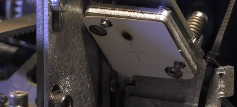
86
00:09:39,950 –> 00:09:49,820
But generally, it takes three steps to get a pretty reasonable coincidence between the target at this point and the target at this point here,
87
00:09:49,820 –> 00:09:56,540
because we’re looking for this laser beam to run perfectly true to this green bearing
88
00:09:56,540 –> 00:10:01,130
rail. And you do all of that by adjusting this mirror.
Transcript for Perfect Laser Beam Alignment Procedure (Cont…)
89
00:10:01,130 –> 00:10:05,850
And that is the procedure for every single axis.
90
00:10:05,850 –> 00:10:19,020
And what we’ve done, we’ve actually made this position here equivalent to the position X here, X and X are now parallel to this bearing rail.
91
00:10:19,020 –> 00:10:30,540
But look, we’re way off center of the mirror. And that could be a problem! When you look at a diameter of the mirror being 25 millimeters like that.
92
00:10:30,540 –> 00:10:36,130
But now if I do this. And I set that mirror at 45 degrees.
93
00:10:36,130 –> 00:10:41,980
We’ve got lots of scope in the vertical direction, we could be two or three millimeters out in the vertical direction, and it not
94
00:10:41,980 –> 00:10:46,270
really worry. Because the beam is not going to hit the extremity of the mirror.
95
00:10:46,270 –> 00:10:52,600
And when we twist it through 45 degrees, we’ve only got about 13 or 14mm of available area.
96
00:10:52,600 –> 00:10:57,760
So in the horizontal direction, we can’t afford to be more than about a millimeter off center.
97
00:10:57,760 –> 00:11:03,790
So if we finish up with a situation like that and this happens to be
98
00:11:03,790 –> 00:11:15,850
from the laser. The only adjustment that we can make is to move the laser in this direction, so that we can allow the beam to go in
99
00:11:15,850 –> 00:11:21,830
to that position. The center of that mirror should now line up with the center of this mirror.
100
00:11:21,830 –> 00:11:29,120
And if you make an adjustment to the tube, the chances are that you will mess up your alignment and you’ll have to go through this procedure again.
101
00:11:29,120 –> 00:11:34,370
That’s an annoying procedure just to get the mirror one lined up.
102
00:11:34,370 –> 00:11:42,140
I have designed a system whereby the laser beam and the mirror are locked together.
103
00:11:42,140 –> 00:11:48,740
I’ve done lots of things to try and make the beam alignment on these machines a lot easier.
104
00:11:48,740 –> 00:11:55,290
Now, I don’t care what the Chinese supply me with, I’d throw it out and I put my own system onto it.
105
00:11:55,290 –> 00:12:01,430
If you go and have a look at RDWorks Learning Lab number 192,
Transcript for Perfect Laser Beam Alignment Procedure (Cont…)
106
00:12:01,430 –> 00:12:07,670
you will see all the changes that I’ve made to my machine to make them easier to set the mirrors.
107
00:12:07,670 –> 00:12:16,280
OK, so we’ve got the beam set onto mirror two, we’re now going to stop the dodgy diagramsfor a little while, because we’re now going to add in some reality.
108
00:12:16,280 –> 00:12:19,100
Now, as I mentioned earlier on in this session,
109
00:12:19,100 –> 00:12:28,970
I take everything that the Chinese put on this machine and basically throw it awa,y because they make beam setting very, very difficult.
110
00:12:28,970 –> 00:12:37,430
I’ve spent some time trying to understand exactly how beam setting works, and I’ve modified my machine in many different ways.
111
00:12:37,430 –> 00:12:49,080
So that it’s easy to set the beam. And I’ll add one other word perfectly. Most people think that after you’ve set X and Y, you’ve got the machine set.
112
00:12:49,080 –> 00:12:57,890
And all you’ve got to do is fire the beam down this tube and twiddle these knobs here to make it come out of the nozzle.
113
00:12:57,890 –> 00:13:06,840
I was one of those people originally, but I have to say I feel rather silly now that I talk about and admit that I was like that once upon a time.
114
00:13:06,840 –> 00:13:14,900
There’s a lot more to it than that. I want to quickly explain why I changed the head design on here.
115
00:13:14,900 –> 00:13:23,130
Now, this design allows me to disconnect the nozzle and the lens tube very quickly.
116
00:13:23,130 –> 00:13:29,750
I don’t have to drop the table to pull the lens tube out of the bottom of the head.
117
00:13:29,750 –> 00:13:35,750
This has also the principle of a V block location for this lens, tube.
118
00:13:35,750 –> 00:13:45,860
Now, V block location is a very, very positive location that keeps the tube fixed in a perfectly upright and fixed position.
119
00:13:45,860 –> 00:13:53,150
You don’t want the lens wobbling around because, hey, look, this is a fairly heavy piece at the bottom here where my finger is.
120
00:13:53,150 –> 00:14:01,280
And if it wobbles around, when you start moving the machine around quickly, that’s not very good for the end result.
Transcript for Perfect Laser Beam Alignment Procedure (Cont…)
121
00:14:01,280 –> 00:14:07,760
In the previous shot, you probably saw that I had this weird G clamp set up on the edge of the machine.
122
00:14:07,760 –> 00:14:17,540
And what I’ve got here is my original C series head that was fitted to this machine, now that weighed about two and a half tons.
123
00:14:17,540 –> 00:14:26,620
I exaggerate slightly, bit it was very heavy. And in addition, the clamp system on here.
124
00:14:26,620 –> 00:14:34,210
It seems like it’s a very good idea because you’ll see that it is a split collar arrangement. For this to slide in and out,
125
00:14:34,210 –> 00:14:39,490
there has to be clearance and clearance means …… Wobble.
126
00:14:39,490 –> 00:14:46,630
So, yes, I know, but when you put the clamp on, that’s going to disappear, so when I tighten this up now.
127
00:14:46,630 –> 00:14:56,040
Quite tight, snug, I’ve supposedly clamped this up and I have, it’s absolutely solid in this direction. But,
128
00:14:56,040 –> 00:15:05,890
I haven’t removed the clearance, I’ve made it, I’ve made the clearance more difficult to wobble. This nozzle can still
129
00:15:05,890 –> 00:15:11,650
move around. There are many other reasons why the head is designed like that.
130
00:15:11,650 –> 00:15:19,270
First of all, it’s got adjustment on a bracket at the back there that allows me to move the head in and out.
131
00:15:19,270 –> 00:15:24,970
We’ve got these screws here which allow me to move the head up and down.
132
00:15:24,970 –> 00:15:35,100
And then additionally, we can just clamp the nozzle in here with my butterfly clamp like that, and of course, I can easily
133
00:15:35,100 –> 00:15:40,170
adjust the nozzle up and down to anywhere Iwant. Especially when you use simple little step gauges like this.
134
00:15:40,170 –> 00:15:50,610
All you have to do is literally just drop the nozzle down onto the appropriate step gauge. And tighten it up.
135
00:15:50,610 –> 00:15:56,220
Focus set! First of all, I wanted to make you aware that I’ve got a head on here,
Transcript for Perfect Laser Beam Alignment Procedure (Cont…)
136
00:15:56,220 –> 00:16:04,230
which has been specifically designed not only for lightness so I can get high accelerations out of this machine,
137
00:16:04,230 –> 00:16:09,060
but it’s been designed for setting. To make things very easy to set.
138
00:16:09,060 –> 00:16:31,620
Nothing is hidden away. Hey now to set the head, we need to make some special targets to make head setting easy.
139
00:16:31,620 –> 00:16:37,080
Now, I’ve previously cut some pieces out of three millimeter acrylic and these are an
140
00:16:37,080 –> 00:16:44,550
essential part of the final setting for your Z axis. Before you glue these together.
141
00:16:44,550 –> 00:16:51,300
What you make sure is that this piece and this do not slide.
142
00:16:51,300 –> 00:16:59,610
In other words, what you want to do is make sure that that, grips in there. Not tightly, but just enough. What we’re going to do, we’re going to
143
00:16:59,610 –> 00:17:10,470
assemble the side pieces first. So we’ll face that towards the right hand side and then we’ll put this one in the same way,
144
00:17:10,470 –> 00:17:16,800
because there’s a flat face here, you’ll notice, and there’s a face with tongues on it down the other side.
145
00:17:16,800 –> 00:17:19,110
Now, this is where you’ve got to be careful.
146
00:17:19,110 –> 00:17:27,870
This flat face has to go to this side and then we’ve got to make sure that the sharp corner goes to the bottom.
147
00:17:27,870 –> 00:17:39,180
And there are two sizes of that. The small one goes on the bottom and the larger one goes on the top and they fit into those two holes there.
148
00:17:39,180 –> 00:17:44,420
OK, now we’re going to drop this one on top here.
149
00:17:44,420 –> 00:17:51,550
That one in there and those two in there. And then with a little bit of pressure,
150
00:17:51,550 –> 00:17:58,840
to keep it all from falling apart. You’re going to stand on it’s edge and then you’re going to drop that piece.
Transcript for Perfect Laser Beam Alignment Procedure (Cont…)
151
00:17:58,840 –> 00:18:08,170
I’ve always got a little bag of helpers here with me because these are essential when you’ve got so many pieces that you want to glue together.
152
00:18:08,170 –> 00:18:15,620
So I picked this up. Carefully, so that it doesn’t fly apart and we put a little helper around the end there.
153
00:18:15,620 –> 00:18:23,420
Now we’ve got my PETG, an acrylic adhesive, which is a bit like water.
154
00:18:23,420 –> 00:18:27,360
I’ve got a very, very small amount in there, as you can see. And all
155
00:18:27,360 –> 00:18:36,550
I’m going to do, is just run that, along that edge there. Along the back.
156
00:18:36,550 –> 00:18:42,640
Along that edge there, and along there. Now I’ve got this on a piece of tissue,
157
00:18:42,640 –> 00:18:51,690
because it soaks up the excess and if you keep it moving around for a few seconds, it doesn’t stick.
158
00:18:51,690 –> 00:18:59,480
And then we’ll just turn it over, and we’ll apply some pressure to that for a few seconds, and then we can run some glue down these edges here.
159
00:18:59,480 –> 00:19:03,190
We’ll put some in that edge there.
160
00:19:03,190 –> 00:19:10,280
So everything is nice and secure now. We’ll leave it for another 10 minutes or so, just for the glue to go really hard and then we can use it.
161
00:19:10,280 –> 00:19:16,120
Now, not everybody will have 3 millimeter acrylic to hand.
162
00:19:16,120 –> 00:19:21,730
I purposely made it of three millimeter because a lot of people have three millimeter material of some sort.
163
00:19:21,730 –> 00:19:34,650
And so in addition to acrylic, there is no reason at all why you can’t make this out of three millimeter MDF or three millimeter plywood.
164
00:19:34,650 –> 00:19:42,960
OK, I know my head has been set up properly, but what I’m going to do now is something that would horrify a lot of people. There we go.
165
00:19:42,960 –> 00:19:47,560
I’ve now messed up the setting on my machine, I’ve got no idea where it is.
166
00:19:47,560 –> 00:19:51,520
But let’s put it back roughly to the middle. It’s always a good point to start from.
167
00:19:51,520 –> 00:19:55,750
We’ve set the Y-axis, but we haven’t yet set the X-axis.
168
00:19:55,750 –> 00:20:01,270
Not true. I suspect that my X-axis is pretty reasonable, but we’ll go and check it anyway.
Transcript for Perfect Laser Beam Alignment Procedure (Cont…)
169
00:20:01,270 –> 00:20:10,000
Technically, once you’ve set your Y-axis, you don’t have to be in a special position to set the X axis.
170
00:20:10,000 –> 00:20:19,180
But in reality, the general rule is that you always set your X axis with the beam, right at the front of the machine.
171
00:20:19,180 –> 00:20:26,980
These targets drop into mirrors one and two. When we look up at mirror three, it’s a completely different animal.
172
00:20:26,980 –> 00:20:34,790
OK, it’s round, but there’s no hole to fix it to, which is why we’ve got a special target.
173
00:20:34,790 –> 00:20:43,390
Looks like this. OK, now it’s got two holes in it which are funny shape and these screws are not a mistake on my part.
174
00:20:43,390 –> 00:20:52,390
I didn’t make them project through because I didn’t have short enough screws. They are through there so that you can plug the target into that position.
175
00:20:52,390 –> 00:20:57,910
So remember what the first action is. We’ve got to make sure the beam is at least hitting the target.
176
00:20:57,910 –> 00:21:02,410
So we put the head as far away as we can. Set my power to about 15 percent.
177
00:21:02,410 –> 00:21:09,000
I don’t want to blow the target off the mirror. I just want to put a little scorch mark on it.
178
00:21:09,000 –> 00:21:16,030
There is. Well, it’s pretty well on center this way.
179
00:21:16,030 –> 00:21:21,370
But it’s a little bit on the low side, but we’re on the target, so we’re not going to worry.
180
00:21:21,370 –> 00:21:28,240
We’ll take that out and we can just turn that round and use the other side of the target as well.
181
00:21:28,240 –> 00:21:34,520
There we are with mirror 3 close up to mirror number two, and we’ll put a mark on there.
182
00:21:34,520 –> 00:21:42,850
So that one’s out target. This is the first move, remember?
183
00:21:42,850 –> 00:21:52,450
Well, as I did say, I have got this axis set up and you’ll see that that mark is completely coincident with the one at the other end.
184
00:21:52,450 –> 00:21:57,580
All right. So we don’t need to set the X axis up because I’ve already got it set
185
00:21:57,580 –> 00:22:01,390
true in both axes. As I said, the machine is already set up.
Transcript for Perfect Laser Beam Alignment Procedure (Cont…)
186
00:22:01,390 –> 00:22:12,430
All I did was mess around with the head. So the x axis is perfect, but it’s way off position, as you can see.
187
00:22:12,430 –> 00:22:17,710
So let’s just explain what we’ve got now, because this is very important.
188
00:22:17,710 –> 00:22:26,020
As we saw when we made that target, it was like that right towards the top edge of the mirror.
189
00:22:26,020 –> 00:22:31,160
So we’ve got here an exact copy of what you’ve just seen.
190
00:22:31,160 –> 00:22:40,700
The beam is hitting the mirror there, but I’m not worried, remember what I said, every axis has got to have the problem broken down into two pieces.
191
00:22:40,700 –> 00:22:45,020
The first part of the problem is to get the beam lined up.
192
00:22:45,020 –> 00:22:49,850
The second part of the problem is to get the beam into the right place on the mirror.
193
00:22:49,850 –> 00:22:55,940
Now, in this case, we’re not going to attempt to put the beam in the right place on mirror three.
194
00:22:55,940 –> 00:23:03,620
Now, we’re going to do that at the next stage. This is a mistake that I made when I was very, very naive.
195
00:23:03,620 –> 00:23:08,640
My next step was to say, OK, so now I’ve now got my beam right.
196
00:23:08,640 –> 00:23:22,220
Let me now move on to the center of this hole. To drop this beam down onto the center of this mirror, which you assume is the center of this hole.
197
00:23:22,220 –> 00:23:27,410
Means you’ve got to go right back to your tube and you’ve got to drop your tube down.
198
00:23:27,410 –> 00:23:33,290
But hang on, you’ve already set your beam into the middle of mirror one and into the middle of mirror two.
199
00:23:33,290 –> 00:23:41,570
You’re now going to compromise those positions to find a good position into the center of mirror three.
200
00:23:41,570 –> 00:23:47,000
No, no, no, that’s that’s totally wrong. You can’t do that.
201
00:23:47,000 –> 00:23:53,000
I know that’s what the Chinese allow you to do and insist you do, because that’s how they’ve designed the machine.
202
00:23:53,000 –> 00:23:58,370
But that is totally illogical. What you’ve got to do,
Transcript for Perfect Laser Beam Alignment Procedure (Cont…)
203
00:23:58,370 –> 00:24:02,880
is allow the head to move up and down.
204
00:24:02,880 –> 00:24:11,100
You can’t afford to have this beam moving up and down and because you’ve already got it set on mirrors one and two,
205
00:24:11,100 –> 00:24:18,510
you’ve now got to catch the beam on mirror three, not set the beam onto mirror three.
206
00:24:18,510 –> 00:24:26,410
The problem when I had my first machine was this. I was trying to get my beam into the center of this hole.
207
00:24:26,410 –> 00:24:29,980
But that didn’t hit something called and I’ll show you this in a second.
208
00:24:29,980 –> 00:24:37,970
The sweet spot on the mirror, the sweet spot on the mirror is actually in line, aligned across there.
209
00:24:37,970 –> 00:24:40,750
I’m about, what, a quarter of an inch above center.
210
00:24:40,750 –> 00:24:48,970
This mirror holder is designed so badly, the sweet spot for the mirror is not in the center of the hole.
211
00:24:48,970 –> 00:24:53,830
Now, that’s not true for everybody’s head. Some heads will be perfectly OK and well designed.
212
00:24:53,830 –> 00:24:58,270
I’m just telling you, that mine wasn’t. And it caused me a lot of grief.
213
00:24:58,270 –> 00:25:04,750
And it’s one of those things that helped me to decide, yes, I’ve got to make my mirror adjustable.
214
00:25:04,750 –> 00:25:11,710
So my mirror is now adjustable in a vertical axis and the and the Y axis.
215
00:25:11,710 –> 00:25:14,470
And you’ll see the reason for that in a minute.
216
00:25:14,470 –> 00:25:27,400
Now, you remember in the last session we went to quite serious lengths to make sure that our table was running true to the axis.
217
00:25:27,400 –> 00:25:40,140
There is a thought that one of the first things you must do is make sure that your lens tube is true to the table in both this axis and this axis.
218
00:25:40,140 –> 00:25:48,130
Okay. Now, if you don’t have the same sort of head that I’ve got here and you haven’t got one of these toys to play with,
219
00:25:48,130 –> 00:25:54,370
then you will have to do just that. You have to make sure that your table and your head are set up
Transcript for Perfect Laser Beam Alignment Procedure (Cont…)
220
00:25:54,370 –> 00:26:08,760
so that it’s completely square. Ok now, we’re hoping and this is the thing, we’re hoping that the Z axis movement, which are these things here,
221
00:26:08,760 –> 00:26:19,000
the lead screws, that are on each side of the table, are in fact all running square
222
00:26:19,000 –> 00:26:29,090
to the axis. They’re a long way away from the axis, and I think they won’t be very far out, but it is an assumption.
223
00:26:29,090 –> 00:26:36,340
And my little toy here. Overcomes that assumption, but if you haven’t got one of these systems,
224
00:26:36,340 –> 00:26:41,290
then you must make sure your head is upright before you attempt to do this. That thing there,
225
00:26:41,290 –> 00:26:50,320
which is your lens has got a curved surface and that curved surface is part of a sphere and there is a center point in a sphere.
226
00:26:50,320 –> 00:26:56,800
In other words, there is an axis, that yellow axis that passes right through the center of that lens.
227
00:26:56,800 –> 00:27:01,990
You won’t have your lens over at an angle because in the bottom of this lens tube,
228
00:27:01,990 –> 00:27:12,370
we’ve got seats and those seats ensure that the lens is both on center and 90 degrees to the axis.
229
00:27:12,370 –> 00:27:26,060
So everything is lined up inside that tube. The only thing that’s not lined up inside that tube, is the beam. Because at the moment, that beam
230
00:27:26,060 –> 00:27:32,480
is bouncing off the mirror. Here.
231
00:27:32,480 –> 00:27:42,200
And it’s coming down the inside of the lens tube. Like this.
232
00:27:42,200 –> 00:27:52,340
Now, when it hits that lens and I’m going to draw another little diagram. I told you I was no good at art. Our laser beam is coming in like this.
233
00:27:52,340 –> 00:28:02,990
The rays of the laser beam are coming in like that. And all those rays are trying to converge on this magical thing here called the focal point.
Transcript for Perfect Laser Beam Alignment Procedure (Cont…)
234
00:28:02,990 –> 00:28:09,530
Having the beam off center is no different to doing this.
235
00:28:09,530 –> 00:28:15,130
Your beam will still pass through
236
00:28:15,130 –> 00:28:19,570
the focal point. Great you’ll say! So it doesn’t matter if the beam is off center.
237
00:28:19,570 –> 00:28:25,990
Well, it does. If you’ve got material that’s that thick, look what your cut is going to do.
238
00:28:25,990 –> 00:28:30,390
Your cut is going to be. Like that.
239
00:28:30,390 –> 00:28:32,370
It’s going to be off angle.
240
00:28:32,370 –> 00:28:42,640
Now, the other thing that could happen is that you’ve got this mirror set up so badly if you bring your beam in, off angle like that.
241
00:28:42,640 –> 00:28:50,030
It’s not going to go through the focal point, it’s going to bounce off further like that.
242
00:28:50,030 –> 00:28:57,510
Bear in mind what we’ve got here. We’ve got a nozzle, with a hole through it. You’re not even going to get out of the nozzle.
243
00:28:57,510 –> 00:28:59,990
OK, so that’s what we’re trying to steer clear of.
244
00:28:59,990 –> 00:29:08,390
And the way that we steer clear of that is to make sure that we put this beam, first of all, parallel to the axis.
245
00:29:08,390 –> 00:29:12,230
And I’m now going to show you how we put the beam parallel to the axis.
246
00:29:12,230 –> 00:29:19,560
First of all, I’ve got to make sure I’ve got an empty lens tube, then we’ll pop that into the corner there like that.
247
00:29:19,560 –> 00:29:28,990
Then we’ll give it a pulse. OK, now we take that and we’ll drop it into the bottom.
248
00:29:28,990 –> 00:29:40,110
Remember? This is like moving the head further away, we’ve moved the target from close in to the mirror to far away from the mirror.
249
00:29:40,110 –> 00:29:51,920
So what we should find now. It’s not bad, it’s not perfectly in line, you can see that the new mark is towards the back.
250
00:29:51,920 –> 00:29:57,990
I’ve now got to adjust the mirror to tip the beam forward.
Transcript for Perfect Laser Beam Alignment Procedure (Cont…)
251
00:29:57,990 –> 00:30:08,690
Now, the way to imagine that is just here, we’ve got a pivot point. And if I want that mirror to go forward. We’ve got to pivot points here, like ahange,
252
00:30:08,690 –> 00:30:15,110
and I’m going to pivot that mirror there by adjusting this little screw here.
253
00:30:15,110 –> 00:30:24,520
So I’ve got to turn that clockwise, probably a quarter of a turn.
254
00:30:24,520 –> 00:30:35,830
It’s not far off. OK, so now all I’ve got to do is I can turn that over because I can use these twice.
255
00:30:35,830 –> 00:30:43,670
Try again. Pop it in the bottom.
256
00:30:43,670 –> 00:30:51,140
So now there we go, we’ve got it in perfect alignment. Wow I did that in two.
257
00:30:51,140 –> 00:30:59,810
Hamg on, I’m off to do my lottery ticket. In Y it’s nearly correct, in X it’s a long way out that way.
258
00:30:59,810 –> 00:31:07,850
So let’s just see what that means. There is an axis that passes right through the center
259
00:31:07,850 –> 00:31:16,120
of the lens tube. And that axis, if you project it up, will hit the mirror at this point just here.
260
00:31:16,120 –> 00:31:20,560
And that point there, is the point that we’re going to call the sweet spot.
261
00:31:20,560 –> 00:31:30,490
That’s the only place on that mirror that will reflect that beam down the axis of the lens tube and through the axis of the lens itself.
262
00:31:30,490 –> 00:31:36,250
I know the Chinese allow you to move the beam by adjusting the tube, but I don’t.
263
00:31:36,250 –> 00:31:41,290
I leave the beam where it is to get that beam to hit that spot.
264
00:31:41,290 –> 00:31:48,250
I’ve got to raise the head. I’m going to move the sweet spot onto the beam. So we will loosen these screws off.
265
00:31:48,250 –> 00:32:01,060
We’ve got to raise the head up. And in raising the head up, we should have
Transcript for Perfect Laser Beam Alignment Procedure (Cont…)
266
00:32:01,060 –> 00:32:08,080
lifted that mirror onto the beam. So let’s just snug these screws up, not tight.
267
00:32:08,080 –> 00:32:13,200
Doesn’t matter whether we do it at the bottom position or the upper position, because we’ve already got this perfectly lined up remember.
268
00:32:13,200 –> 00:32:22,900
Not enough, too much! Dam the expense, lets use another target.
269
00:32:22,900 –> 00:32:30,670
I think we’re pretty happy with that. You can see it didn’t take very long at all to do this most difficult part of the process.
270
00:32:30,670 –> 00:32:37,630
I’ve got to get the beam right through that hole. If I’ve lined this up properly, it will come through the middle of the hole.
271
00:32:37,630 –> 00:32:42,830
Now, we’ve got another little laser beam alignment tool for doing that.
272
00:32:42,830 –> 00:32:48,540
It’s this little thing here, which I’ve just, I’ve got some old tape on here, but I think that will be ok. There’s a nice, clear one there.
273
00:32:48,540 –> 00:32:53,310
So we just put that on the end of the nozzle like that and we go beep.
274
00:32:53,310 –> 00:32:59,640
And there it is look, right through the middle. It’s probably taken no more than 10 minutes for me to reset that
275
00:32:59,640 –> 00:33:02,190
beam. If I was to start right from the back,
276
00:33:02,190 –> 00:33:09,170
I could reset the whole of this machine up, in about 15 minutes and make sure I’ve got it just perfect like that.
277
00:33:09,170 –> 00:33:14,100
One final check that I forgot to tell you about. That is a killer.
278
00:33:14,100 –> 00:33:23,020
It will make you tear your hair out if you’re not careful. We’ll drop our target in there and we’ll make a mark.
279
00:33:23,020 –> 00:33:33,640
Spot on! We can’t ask for better than that, can we? But now what we’re going to do is to move it to the back corner.
280
00:33:33,640 –> 00:33:39,250
If it’s not spot on, there’s an additional step that you must take. Look,
281
00:33:39,250 –> 00:33:45,370
I’m right over in the back left hand corner of the machine and I need to make a scorch mark there.
282
00:33:45,370 –> 00:33:50,800
That’s my target. So from the back left hand corner, we move to the front right hand corner.
283
00:33:50,800 –> 00:33:57,070
But if there’s an error along the way down your Y or your X-axis. If they’re not perfectly aligned,
Transcript for Perfect Laser Beam Alignment Procedure (Cont…)
284
00:33:57,070 –> 00:34:02,410
then you will generate an error here between that back corner and here.
285
00:34:02,410 –> 00:34:11,010
So you’ve got to now do a final check. You will adjust mirror one to bring the dots
286
00:34:11,010 –> 00:34:19,060
coincidental. It will require the very, very smallest amount of adjustment, on mirror one to get the two spots to line up.
287
00:34:19,060 –> 00:34:24,370
I’m happy that that machine is pretty close to perfect! I’ll metaphorically
288
00:34:24,370 –> 00:34:34,240
take a bow and see you in the next session.
Disclaimer
Last updated August 26, 2021
WEBSITE DISCLAIMER
The information provided by n-Deavor Limited, trading as Laseruser.com (“we,” “us” , or “our”) on (the “Site”) is for general informational purposes only. All information on the Site is provided in good faith, however we make no representation or warranty of any kind, express or implied, regarding the accuracy, adequacy, validity, reliability, availability or completeness of any information on the Site.
UNDER NO CIRCUMSTANCE SHALL WE HAVE ANY LIABILITY TO YOU FOR ANY LOSS OR DAMAGE OF ANY KIND INCURRED AS A RESULT OF THE USE OF THE SITE OR RELIANCE ON ANY INFORMATION PROVIDED ON
THE SITE. YOUR USE OF THE SITE AND YOUR RELIANCE ON ANY INFORMATION ON THE SITE IS SOLELY AT YOUR OWN RISK.
EXTERNAL LINKS DISCLAIMER
The Site may contain (or you may be sent through the Site) links to other websites or content belonging to or originating from third parties or links to websites and features in banners or other advertising. Such external links are not investigated, monitored, or checked for accuracy, adequacy, validity, reliability, availability or completeness by us.
WE DO NOT WARRANT, ENDORSE, GUARANTEE, OR ASSUME RESPONSIBILITY FOR THE ACCURACY OR RELIABILITY OF ANY INFORMATION OFFERED BY THIRD-PARTY WEBSITES LINKED THROUGH THE SITE OR ANY WEBSITE OR FEATURE LINKED IN ANY BANNER OR OTHER ADVERTISING.
WE WILL NOT BE A PARTY TO OR IN ANY WAY BE RESPONSIBLE FOR MONITORING ANY TRANSACTION BETWEEN YOU AND THIRD-PARTY PROVIDERS OF PRODUCTS OR SERVICES.
AFFILIATES DISCLAIMER
The Site may contain links to affiliate websites, and we receive an affiliate commission for any purchases made by you on the affiliate website using such links. Our affiliates include the following:
- makeCNC who provide Downloadable Patterns, Software, Hardware and other content for Laser Cutters, CNC Routers, Plasma, WaterJets, CNC Milling Machines, and other Robotic Tools. They also provide Pattern Files in PDF format for Scroll Saw Users. They are known for their Friendly and Efficient Customer Service and have a comprehensive back catalogue as well as continually providing New Patterns and Content.
- Cloudray Laser: a world-leading laser parts and solutions provider, has established a whole series of laser product lines, range from CO2 engraving & cutting machine parts, fiber cutting machine parts and laser marking machine parts.