 Skip to content
 The Fiber Laser Learning Lab Series with Russ Sadler
In this Series, Lotus Laser have lent Russ a MOPA 20 watt fiber laser to “play with”. Although Russ has a moderate understanding of laser technology (his words) and how constant power glass tube systems work, the fiber laser engraving machine is shrouded in a deeper mystery than the glass tube machines.
They have been designed for high speed marking and the technology has been well tried and proven. There are limited “tricks” that the pulsing laser technology can perform. You enter predefined parameters for each marking “trick” you wish the machine to deliver , then stand back in amazement. Most correspondents tell Russ that they have bought their machine direct from China and received a machine and EZCAD software, preloaded with a few default parameters. No other instructions beyond the EZCAD manual are forthcoming.
Russ states “I am neither a teacher or expert in this field so you join me in my learning adventure with the warning that I have a simple but inquisitive mind and will probably make mistakes on my way to discovering the truth. I WILL oversimplify and maybe distort the scientific detail in my quest to build a simple picture of why and how this technology works. I am not trying to reverse engineer anything, just to break through the seemingly impenetrable ‘techno cotton wool’ that surrounds this amazing piece of science.”
Contents
In this session, Russ discusses how he has been repeatedly warned about the risk of back reflection of the laser beam from “Shiny” surfaces. So he investigates the topic further to determine the actual risks involved
Video Resource Files
There are no more resource files associated with this video.
External Resource Links
There are no more external resource links associated with this video.
Transcript for Fiber Laser Engraving Machine: Back Reflection
Click the “Show More” button to reveal the transcript, and use your browsers Find function to search for specific sections of interest.
0:00welcome to another fiber laser Learning Lab I might look as I’m relaxing this
0:09thing up here is gone bonkers I’m having all sorts of problems trying to
0:14understand something a major feature of this machine I spoke about it and I
0:20think it was the last session it’s a danger called back reflection which I’m
0:27told can cause very serious damage to this machine I’ve been warned that you
0:34first of all you need to be very very careful about where you set the focus on shiny materials shiny is a bit of a
0:42misnomer because it’s not a shiny surface that you’re worried about it’s a reflective surface and they’re
0:49not necessarily exactly the same thing a reflective surface will be something like gold or silver yeah looks as though
0:58I’ve got lots of that I’m gonna play with on the machine here doesn’t it or something that I have got which is almost the same level of reflection as
1:05cover now shiny stainless steel you would think is reflective it’s not quite
1:12as reflective as you think and it’s all down to the crystal structure or the
1:17atomic structure of the material itself but we’ll come on to that a little bit
1:23later the biggest problem I’ve got is trying to understand just how the actual
1:29rays I call them Ray’s because that’s what other people call them beam how the
1:36beam can reflect back on itself I don’t imagine the beam as being a beam
1:43I imagine the beam as being like a herd of sheep it’s an entity of photons each
1:50photon is a separate item but I’m not a physicist and I think that’s really the
1:57wrong concept and may well be a confusing concept I’m yet to try and find that out I suppose you could regard
Transcript for Fiber Laser Engraving Machine: Back Reflection (Cont…)
2:05it almost like a tsunami as I’ve mentioned that word before the tsunami as a tsunami is a wave
2:10a huge wave of energy and I suppose photons when they all act together are
2:15just like that a big wave of energy but every one of those photons is a separate
2:23entity inside that wave so it is both at the same time a collection of bits
2:28pieces elements the photons and the entity which is the wave and it is the
2:35wave that maybe does the damage although the wave is a collection of photons very
2:41confusing I’m trying to get that picture in my mind when I should imagine one thing or when I should imagine something
2:48else the other thing that I’ve been told and I hope I don’t disbelieve this at
2:53all because this is from a very eminent physicist is that photons when they act
3:00together in total parallelism if they get out of synchronism they’ll cancel
3:05each other out and you’ll get nothing but when they collide with each other unlike two streams of water for example
3:12which when you hit them together just cups photons just don’t care about each
3:18other they can exist in the same space and can pass each other so from that point of view I can understand what back
3:25reflection is if you get a photon reflects off the surface it will not cancel out by an oncoming photon even
3:33though it collides with it well that’s what I’ve been led to believe so I’ve
3:39got all these confusing concepts in my brain at the moment which I can’t really put together and make sense of when
3:45people talk about the dangers and the damage of back reflection from this machine so today we’re going to do a
3:54little bit of an analysis from a practical point of view I’ve trying to find out what’s going on so we’re gonna
Transcript for Fiber Laser Engraving Machine: Back Reflection (Cont…)
4:00do some rather strange things today which I very much doubt with a many people have done before but this is not
4:05a NASA laboratory I don’t have any sophisticated equipment there if I have to be very inventive with the very basic
4:12pieces of kit that I’ve got but quite often you can get very good not accurate
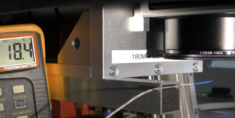
4:17but good answers basic equipment now what I’ve got on the work table here is a piece of wood which
4:24we know will not be affected by the beam in any way shape or form I’ve set the beam to go backwards and
4:30forwards this way so I know roughly where the beam is as it comes out of the lens it’s not going to change very much
4:36its position at all because remember down here it’s a long way away from the lens that means when it comes out of the
4:43lens there’s going to be virtually no movement on that beam at all when the beam hits this thermocouple
4:48there will be a heating effect so as the beam scans backwards and forwards if it
4:55manages to hit the thermocouple it should raise the temperature and that tells me where the edge of the beam is
5:01and then I can approximately work out what the diameter of the beam is when it
5:07comes out of the lens which is quite an important fact for me because I want to work out what the angle of the cone is
5:13that gets me down to the focal point just on the edge of the red beam there I’m going to pull it back just a shade
5:22there we go we’re working now wow look we’ve got some results so we know where
5:28the beam is so we’ve hit the edge of the beam there somewhere let’s just see
5:33let’s draw it back a little bit further run the test again
5:41no effect so let’s just edge it forward just a
5:47shade again and there we go so we found the edge of the beam I’ll put a black
5:54mark on there so this is not continuous beam passing over that thermocouple it’s just very quickly scanning over it
Transcript for Fiber Laser Engraving Machine: Back Reflection (Cont…)
6:01leaving a little bit of energy behind getting towards the middle the beam now so let’s just see if we can find the
6:09highest power 180
6:21264 certainly up there somewhere it’s
6:28approximately the center so let me mark very carefully that as well okay so
6:37there’s my two marks on there and I would say there are about two millimeters apart so that represents the
6:44center to one half of the beam which would indicate that the beam is probably
6:49around about four millimeters diameter but of course that isn’t entirely true
6:55because remember it is a Gaussian distribution and probably I’m not
7:00picking up the tails of the beam I’m only picking up the most powerful part of the beam that’s enough to heat the
7:08thermocouple so it’s very likely that the beam might actually be as wide as
7:15they claim which is a seven millimeter beam and I’m only picking up maybe four
7:21millimeters or maybe four and a half millimeters that that beam these are two zinc selenide lenses on the co2 machine
7:29they’re fairly short focal lengths and I knew what I was doing when I tried to
7:35engrave stainless steel with them now as
7:41I said I knew what I was doing and I knew there was a risk of reflection and here’s a good example of exactly what
7:47happens these lenses only some 40 millimeters above the surface of the material the one on the right look as
7:53heated up the front face of the lens and it’s actually cracked right the way through the lens itself and the one on
Transcript for Fiber Laser Engraving Machine: Back Reflection (Cont…)
8:00the left I’ve managed to burn the anti-reflective coating off the face of the lens the optics can be damaged by reflections I
8:08have no doubt how I can manage to achieve it with a lens system which is
8:15254 millimeters above the work surface I’m struggling with now often make it
8:23clear I’m not a teacher I’m on a learning journey I’ve got a lot
8:29of elemental facts about how lasers work and how materials up right but sometimes it’s a bit like
8:38having a jigsaw puzzle when you first open the box all the pieces are there but they don’t actually make any sense
8:44and that’s the problem I find quite often so one of the techniques that I
8:50use to try and help organize my thoughts is to write a document and put things down in a logical order and that’s what
8:57I’m attempting to do here I’ve got a series of titles here subject titles which I’m going to go through now I’m
9:02not going to apologize that some of these I’ve already discussed with you before but we’re going to discuss them
9:09again because they form part of this logical chain of working towards an
9:14answer now at the moment I’m giggling to myself here because I don’t have an
9:20answer I’ve still got the same confusion that I had when I made the first part of the video but I’m fairly confident that
9:28by the time we work our way through this list we will arrive at a sensible answer
9:34I shall probably have to do some research in the meantime but this is taking several days to create this video
9:40this is not quite the live video that I normally do so let’s push on and make a
9:48start now my early sessions of this series explained how an excited electron
9:56manages to be disturbed by a passing photon and it drops down to a lower
Transcript for Fiber Laser Engraving Machine: Back Reflection (Cont…)
10:02energy level and then dropping down to a lower energy it emits something called a photon of light got no mass but it
10:08somehow has energy and as it goes past excited electrons it drags them all down
10:15and they just like this picture here they all remain phase synchronized doesn’t mean to say they’re all together
10:22but they remain basically locked together in the same sort of phase now
10:27this is a problem of having trying to decide when these little my new entities
10:34turn into something else but when they turn into something else they become more powerful you can pause the video
10:41and read what it says I come across this this concept that a beam of these
10:48Tong’s is a collective term and even though the photons remain individual
10:54little packets of energy just like sheep in a herd they can never be one big
11:00sheep they are just a herd it can be persuaded as an entity to move in
11:07different directions for example a sheepdog herding the Sheep will move the
11:12Sheep regard the sheepdog if you like is an external influence but it’s affecting
11:19the whole of the the wave it’s not just affecting one sheep when they’re all travelling in the same direction as a
11:25laser beam they technically should all be in-phase if for some reason they get
11:31out of phase then they will cancel and there will be no energy no light but
11:37we’ll come back to this little subject here in a minute this is this is what I have read so far my two gray cells are
11:44very easily confused when waves collide they will add or subtract but when
11:51photons collide they just passed through each other I’m glad I’m not a physicist now a photon is a little packet of
11:58energy which is a fixed packet of energy it has a certain if you want to imagine it as a wave if it has a certain
Transcript for Fiber Laser Engraving Machine: Back Reflection (Cont…)
12:05amplitude or volume you can’t change that so if you want more light intensity
12:11or light density you need to pack more photons into the same physical area or
12:17volume so therefore I suppose if we imagine a single photon as being like a
12:22raindrop it will have very little damage potential but if you put millions and
12:29billions and gazillions of them together and move them in unison that now becomes
12:34a wave imagine a tsunami look at the potential damage you can do with the
12:40tsunami wave the beam on is 20 watt fiber laser machine is basically no
12:46different than the format of the beam on the co2 gas discharge later and what I’m
12:52saying here is the density of the photons is maximum right at this point
12:57here right down the center okay this is the highest point on the graph this is the greatest light intensity and the
13:04greatest light intensity means we’ve got maximum density of photons okay now this
13:10is a seven millimeter diameter beam so very crudely let’s just say that it’s
13:16six millimeters diameter because that makes it nice and easy to look at what we’ve got here then we’ve got one two
13:21three four five six sections so the centre two millimeters of that beam if
13:29it’s a 20 watt beam contains thirteen point six watts there’s no such thing as a section of
13:36the beam these are just convenient breakpoints to show you approximately what’s happening within
13:43the beam the next section out which is another millimetre on either side of the
13:48centre we’ve got only 2.7 watts and right on the outside we’ve got half of
13:55nothing so really the only moderately
Transcript for Fiber Laser Engraving Machine: Back Reflection (Cont…)
14:01powerful part of the beam is the central two millimeters even though it’s a seven millimeter diameter beam and that’s a
14:09very important point to remember now a hundred percent power is not twenty
14:15watts twenty watts is down here if we chop the graph off across that 20 watt
14:20line and we should be able to take the top half of that graph and we’ll be able to fill in the gaps at the bottom here
14:27okay so that’s roughly what that 31 percent is that 31 percent of a hundred
14:33percent power as where our 20 watt average power is and if we like to consider then that 100 percent power is
14:40probably 65 Watts right at the peak so we’ve got 20 watts average power but
14:45probably 65 watts available to us at the peak now I’ll leave that part on the
14:51screen just in case you want to read it but I’ve just described what that says now in this section we’re not actually
14:59going to talk about how the lens focuses that’s a completely separate section
15:04that I’m going to come onto next what we want to do is look at how the light gets affected as it passes through the lens
15:11now this was another big problem that I was having trying to understand the concept of first of all what happens
15:18when the light hits the lens now I know enough about physics to know that when a
15:24ray of light hits a surface it gets refracted now refracted means change
15:31direction or does it it also means that it changes speed the light within the
15:40glass or that medium reduces its speed it slows down how can light slow down
15:57you now although this is not field glass
Transcript for Fiber Laser Engraving Machine: Back Reflection (Cont…)
16:04it’s a glassy type material and the light will slow down inside the glass to
16:09about 200 million meters a second yeah
16:15okay that’s not really slowing down is it but it’s it has reduced by about a third this ray of light here enters at
16:23300 million and travels that distance this ray of light here enters at 300
16:28million and traveled that distance now as it goes in and slows down this ray
16:35here must exit before this right here okay so there no possibly no longer a
16:42laser beam because they must be out of phase reading between the lines I’ve
16:49been advised by very learned physics professor that I’m basically an idiot I
16:54didn’t need to be told because I know that already as I said I’m an engineer not a physicist and I don’t know how a
17:00physicists mind works certainly this stuff is almost like reading Chinglish but what I am and can
17:09understand is although this ray here exits before this ray here it has
17:16further to travel to get to the focal point so although it resumes its journey
17:22sooner it will get there later because it’s got further to travel and although
17:29this one exits later it will get there sooner because it’s got a shorter distance to travel and the
17:36idiot part of it was it wouldn’t be a lens if they didn’t all arrive at the same time that’s the whole point of a
17:43lens okay so I didn’t know that so I’ve just described what that text says but
17:49I’ll leave it on the screen so you can pause and read it if you wish okay now we come on to something rather interesting which gets us into a very
17:58controversial area because this is not an area where I can find any information
Transcript for Fiber Laser Engraving Machine: Back Reflection (Cont…)
18:06the only information that I’ve got is information that I’ve developed for myself
18:12the is lens theory and everybody seems to rely on lens theory and not what happens
18:20in practice and I have had to investigate what happens in practice because I could not make lens Theory
18:28agree with what I was observing you cannot focus liked to appoint any
18:35smaller than its wavelength so the smallest possible spot we could get for
18:42this fiber laser is roughly 1 micron now
18:48the problem is it would be incredibly expensive to make a lens which
18:53physically focus down to the theoretical minimum 1 micron and in reality all
19:01lenses have got something called aberration which means that they do not
19:07pass through this theoretical focus point you will see the path of light
19:12described through a lens in the way that I’ve shown it on this diagram here that’s totally ludicrous because light
19:19cannot bend around corners so how does this diagram come about if we take a
19:27look at this Plano convex lens that I’ve drawn here you’ll see that the Rays from the outside of the lens are crossing
19:35over at a focal point which is less than where the arrow shows D and those rays
19:45they’re coming down the center of the lens are crossing over substantially
19:51beyond D and the profile that you see in
19:58the picture above has been sketched in there to show you that basically what
Transcript for Fiber Laser Engraving Machine: Back Reflection (Cont…)
20:03you’ve got it’s that outline which encapsulates all the beams that are going towards the focal point focal
20:12point is a bit of a misnomer I like to call that D are a fuzzy focal point
20:20because the closer the beams are to the axis of the lens the further they
20:26crossover beyond – the actual focal point and very conveniently this diagram which I’ve
20:32picked up happens to be approximately three divisions on either side of center
20:38line now if you want to go back to the beginning and take a look at the distribution of light energy in that
20:45beam hitting the lens remember we’ve got roughly 70% of the light energy within
20:55those two central rays so therefore that maximum intensity of light than the
21:01center of the beam is actually focusing quite a long way beyond the nominal
21:07focal point so this is a very confusing practical situation we’ve got a very
21:13rapid or company here – six who make all sorts of optical systems very very high
21:19laboratory and industrial lenses two very important points we must note
21:26spherical aberration increases the spot size now let’s just turn that on its
21:31head for a moment and say if the spot size was theoretically perfect for this
21:38machine and with this lens we would have a 1 micron spot size we do not have a 1
21:47micron spot size on this machine we’ve got a 254 millimeter long focal length
21:52lens which has got a claimed spot size of about 65 microns that’s a
21:59lot more than the theoretical 1 micron that it could be and what we’re saying
Transcript for Fiber Laser Engraving Machine: Back Reflection (Cont…)
22:05is 65 microns is pretty pretty damn good but what it does mean to say is we’re
22:13accepting a lot of spherical aberration now this will be important later on now
22:19the other thing that it’s clearly stated here is that this also causes the best
22:25focus to occur at a different location than the theoretical focal point notes
22:31on being cynical about the word theoretical I personally think that the phrase best focus is a little bit
22:38confusing in its own right focus employee a single point and as you can clearly
22:44see there is no single point what we have really is an integration of the
22:50intensities of all the Rays which come together at a single point where we get
22:56maximum light intensity so let’s come back to our seven millimeter diameter beam and we know that it’s roughly seven
23:04millimeters diameter because when we measured it at the beginning of this video we clearly saw that we had power
23:10roughly plus or minus two millimeters from centre and where’s plus or minus
23:17two millimeters from centre it’s that point where we’ve got maximum intensity
23:22we’ve got very little power beyond plus or minus two millimeters if you look at
23:28this graph here so instead of using the absolute spot size as defined by JP T
23:33for this particular machine I’m going to use a closed equivalent which is 0.07 70
23:40microns as opposed to 65 microns and the reason for that is because it’s a very nice factor of seven millimeters so what
23:48I’ve done I’ve taken the light intensity from a seven millimeter diameter beam and I’ve squashed it down to point zero
23:55seven as shown by the little picture on the right hand side there which means I
Transcript for Fiber Laser Engraving Machine: Back Reflection (Cont…)
24:01have now increased the intensity by a factor of seven divided point point zero
24:08seven which is a hundred times what occurs at the focal point is still a
24:13Gaussian distribution when we amplify the power we take every single part of
24:19that graph that you can see here and we multiply its amplitude by a hundred if
24:27we look just here there’s the little Gaussian distribution that we had to
24:32start with but it isn’t like that now but the time we multiply every one of those amplitudes by a hundred so we’ve
24:39got a huge spike of energy at the center of this beam now now I don’t wait to run
24:46away with the idea that this is a drill or anything like that this is a graph of
24:53the intensity of light but obviously because we’ve got so much light intensity here at the center of the beam
25:02it’s going to have an influence way beyond the focal point itself because
25:07this beam is symmetrical on its way to the focal point and away from the focal
25:14point it clearly implies that we’re going to get exactly the same spike of
25:20energy above the focal point as well as below the focal points that are going to
25:25get this strange central core of energy around the focal point above and below
25:31it but extends both up and down from the focal point if we take a look here at
25:37what jpt tell us about the lens itself they tell us that there’s a focal length
25:44254 millimeters which is what I’ve got on this machine those who tell me that it’s roughly what sixty three point nine
25:5064 microns for the spot size across here
25:56okay they then go on to tell me that we’ve got something called a depth of
Transcript for Fiber Laser Engraving Machine: Back Reflection (Cont…)
26:02field or depth of focus which extends in this particular instance to two
26:07millimeters ie one millimeter above and one millimeter below the nominal focal point we’ve got
26:16a useful working power from other work that I’ve done this depth of field stops
26:23at a point where approximately the area of the beam is twice the area of the
26:30waist so if we’ve got a certain energy density at this point here it will be
26:37half the energy density there and that approximately defines the working depth
26:42of field for a lens so at that point the beam starts to go out of focus this is a
26:47difficult concept for people to actually grab hold of I’ve tried to explain at many many times in my work and this is
26:55where theory and practice tend to diverge this is the practice that I’ve
27:01come across and I know that I can produce a lot of damage way beyond the
27:07focal point this is the method by which the laser focus the machined we fiddle with
27:12the lens and we adjust the height up and down above and below the focal point
27:18this is above the focal point and this is below the focal point until we get
27:23symmetry now if we were getting symmetry
27:29because the beam was going out of focus it would start going out of focus
27:35according to jpt at plus or minus one millimeter we should find that we’ve got
27:41a 65 micron line just there in the center but the time we get out to plus or minus one millimeter we should see
27:48that line growing to 90 microns does that look like a 90 micron line no it
27:56looks exactly the same as that 60 micron line what about at 2 millimetres no that
Transcript for Fiber Laser Engraving Machine: Back Reflection (Cont…)
28:02hasn’t grown either and at 3 millimeters no so wherever we go along this graph
28:08we’ve got the same thickness of line so we cannot be going out of focus with
28:15this line what we’re running out of is damage power you’re here now the top
28:21picture was done when the power was set to 100% now let’s just backtrack for a
28:26second and how do we get to that picture there well we got to that picture by
28:32multiplying this graph by a hundred if we take this graph and reduce the power
28:39to 50% it’s going to get shorter and smoother it’s going to get blunter okay
28:47it’s amplitude is going to get less because we’re now going to multiply this
28:54graph by a hundred because we’ve still got the same lens which multiplies by a
29:00hundred but we’re multiplying a smaller graph by a hundred so we no longer have
29:07this very sharp-pointed 100% power we shall have something that’s roughly half
29:12the length and it will have less of a point on it it will still be sharpish but it’ll be blunter it’ll be softer
29:19gentler at its maximum intensity point so now we can begin to maybe understand
29:26why this picture at the top here is actually different to the picture at the
29:32bottom this is 50% power the influence beyond this so-called focal point here
29:39which we’ve defined has grown we’ve got a much longer length of influence of
29:46that intensity so it’s no longer able to just do damage at plus or minus three
29:52millimeters it’s now able to do damage at plus or minus six millimeters so we
29:58would just refer back again that we should theoretically I’m being cynical again be getting a 90 micron thickness
Transcript for Fiber Laser Engraving Machine: Back Reflection (Cont…)
30:06at these plus and minus 1 millimeter points who knows what was your beginning at 3 or 4 5 & 6 millimeters you know
30:15there is no thickening of these lines we’re not picking up the out-of-focus
30:23part of the beam what we’re picking up here is the central core of energy in the beam this core of light intensity
30:33and that’s the difference between the theoretical focus point and what I’m
30:40describing to you is the practice that actually happens within a lens doesn’t
30:47just stop and go out of focus now this takes me back to the point where Lotus
30:52later asked me to make sure that if I tell you guys to use the focus as one of
31:01the parameters for limiting the power that you do it by moving the work
31:07towards the lens and not away from the lens I can accept what they say but I
31:13need to understand what they’re saying and why the first thing that I can see here is that when they set the Machine
31:19up they’re automatically going at least 3 millimeters below the focal point to set up zero now the zero that they’ve
31:26actually found is this point here point at which you get maximum energy density
31:32now remember this energy density graph is not only below the focal point it’s all so above the focal point so if I find
31:39the matching extremities above and below the focal point which is what I’ve done here and we could call that the focal
31:46point but I do know that this zero here is not that zero there and now we’re
31:56going to go on and try and explain why and to do that we need to look at this thing that I called earlier fuzzy focus
Transcript for Fiber Laser Engraving Machine: Back Reflection (Cont…)
32:04we absolutely know that this lens has got aberration I’ve drawn this picture
32:12here on my CAD and yeah it’s designed to be a graphical representation of what’s
32:21happening in the B light rays travel in straight lines they cannot bend around corners and unless they’re affected by
32:27gravity or some other major effectors Einstein proved but what it does show me
32:33is that out of 254 millimeters long the red raise the outer rays which you’ve
32:40got insignificant amount of energy in them focus at roughly 2 3 4 5
32:49millimeters I don’t know exactly what the number is but I can be sure that it is some number of millimeters before and
32:56above the focal point this is the extremity of the blue section now which
33:02contains another 20% roughly of the energy that focuses maybe 3 4 5 again
33:12millimeters beyond the focal point and
33:18wherever that focuses the central core focuses another 4 5 6 millimeters beyond
33:28the blue zone so when we zoom in and look at actually what’s happening at the
33:35focal point this nominal focal point just here where my 70 microns spot is we
33:42can see that the blue zone was crossing here
33:48and the yellow zone as crossing substantially further forward but bear
33:54in mind that this yellow zone I’ve drawn is not at the center axis of the lens
Transcript for Fiber Laser Engraving Machine: Back Reflection (Cont…)
34:02these are the extremities of the yellow zone as I get closer and closer to the
34:09center of axis of the lens this crossing point this focal point of that yellow
34:16zone is going to go out here to some stupid extreme I mean it’s just a fact
34:21of geometry if you make two lines parallel they will never cross but it is that intense part of the beam which is
34:28focused beyond the focal point I cannot tell you how much all I can demonstrate
34:35to you is the principle and not the theory the practice that they will
34:40absolutely focus beyond this nominal focal point that then asks the question
34:48where is this integration of power we’ve
34:54got the red beam there which is carry nothing but a hint of something we’ve
35:01got the blue beam which is moderately powerful and we’ve got the yellow beam which is carrying 70% of the energy of
35:10this beam by inference the yellow beam
35:16is going to win there’s going to be an addition and an integration of the blue
35:22beam as well but what we’re really saying is look just take a look at my
35:27little top picture there where it says three point six one and four point six okay that means the yellow beam is
35:34roughly a millimeter beyond the blue beam which is not really true because
35:40that yellow beam is lightened to be meters effectively beyond the yellow
35:46beyond the blue beam once it gets to its extremity let’s just guess and say that the integration point where we get
35:53maximum intensity of all these beams combining as five millimeters below the
35:59focal point so this is where the confusion comes in we’re happy to agree that at this point
Transcript for Fiber Laser Engraving Machine: Back Reflection (Cont…)
36:06here we’ve got the integration of all the beams giving us the most intense point that’s not necessarily the focal
36:15point that’s just the point of maximum energy density but where is that point
36:22of maximum energy density in relation to the nominal focal point the answer is
36:28probably four five six millimeters below the nominal focal point I don’t know I
36:34can only show you in principle that it is not at the focal point okay now let’s
36:40just leave the uncertainty of the focal point itself for a moment and we’ll push on with something more important which
36:47is the material that we go to fire the laser beam at now we’ve got these three
36:55simple diagrams here the most important thing in the first diagram is that dotted line which is something called
37:01the normal that’s the point of perfect perpendicularity to the surface and when
37:07you fire a beam at the surface it will always reflect relative to that normal
37:13if the reflected ray is exactly the same as the incident ray then we have a
37:19lovely mirror reflection now the next two pictures show the types
37:25of surface that we’re going to be firing the laser beam at the first one is
37:30called a specular surface where the reflection bounces off exactly as a mirror reflection it applies that very
37:37simple rule all the Rays are bouncing off in a parallel direction and if you were looking at yourself in the mirror
37:44you would see the handsome person that you are now if you go to the next
37:50picture along which is a diffusive reflection where the surface now diffuses the light rays into random
37:58paths it obeys all the same rules as the first image mirror reflection but at the
Transcript for Fiber Laser Engraving Machine: Back Reflection (Cont…)
38:04point where the ray hits we take the normal to the surface at that point and
38:10calculate the new angle of reflection and as you can see because the surfaces irregular the normals would
38:18not be parallel to each other therefore the reflected rays will not be parallel
38:23to each other and this is a bit like looking itself in a distorted mirror if
38:29you can see anything at all now the other thing that’s important about reflection it’s all to do with the
38:35wavelength of light the sort of materials that we’re worried about are metals and all metals have got a very
38:42dense crystalline structure where the atomic particles are very closely bound
38:49together if we have a short enough wavelength then that wavelength is able
38:55to penetrate into the gaps between the atoms and all of a sudden the light
39:01becomes absorbed but if the atomic distance is smaller than the wavelength
39:07of light that you fire at it then we will get a specular reflection we will
39:12get no penetration of the light into the surface of the material now we can begin
39:18to see that phenomenon in this little diagram here this is the wavelength of some typical materials that you will be
39:25using with this machine the blue one is aluminium then we’ve got gold which is red and silver which is the black one
39:32now if we take a look at the wavelength scale along the bottom we’re working
39:37with roughly one micron now as you can see above one micron we’ve got something
39:44like I don’t know 95% or more reflectivity at one micron
39:52things are starting to change very slightly if we drop down to 500 and
39:57maybe 400 nanometres you could see the serious drop off in the reflectivity of
Transcript for Fiber Laser Engraving Machine: Back Reflection (Cont…)
40:03gold and silver that’s because the atomic spacing is such that at those
40:10points there the waves are actually penetrating into the material and being absorbed they’re no longer being
40:16reflected now our concern in this video is all about reflectance off of the surface of materials now the only
40:22materials that are really going to be at risk for us are these sorts of materials
40:27here in this table and you can see that at 10 microns where we may be used to working with the co2
40:33laser all of these materials are incredibly reflective it does change for
40:39some of these materials as we get down to one micron and that little table there shows you the risk associated with
40:46using these materials okay I think we’ve now collected all the pieces of the jigsaw puzzle that will enable us to
40:52probably go forward and try and decode the subject to this video which is back reflectance now we’re going to use this
41:01diagram quite a few times in our discussion um and it’s important that you understand what it actually is I
41:08know you can look at it and say yeah I’d say that’s a lens with some light rays going through it yes but this is a
41:14simulation of an F theta lens this is not an F theta Lin and F theta lens is a
41:20very special three-dimensional version of a lens because it sweeps through a
41:26spherical orbit and wherever it is in that orbit it has to focus that’s a very
41:31complex thing to even try to draw let alone to work with so what we’ve got here is a simple Plano convex lens which
41:39exhibits all the same properties as this 3-dimensional F theta lens but it’s
41:45condensed back into two dimensions where it’s much easier to comprehend what’s going on now this is not just some
41:52random drawing that I’ve created and out of my imagination the lens itself is a
41:58creation but it’s a creation with a circular arc on the top of the lens now
Transcript for Fiber Laser Engraving Machine: Back Reflection (Cont…)
42:05the circular arc represents a part of a sphere and normally a lens would have a
42:10spherical top surface so this is a section a centerline section through a lens because it is a geometric surface a
42:17part of a spherical surface it possesses something called spherical aberration and as I’ve described before spherical
42:23aberration is when it rays from the outside focus at a different point to
42:30the rays passing closer to the axis of the lens what I’ve done here I’ve drawn
42:35the horizontal ray lines and I’ve used the same colors that I’ve used in the Gaussian distribution
42:42so that you can keep that in mind that the yellow section down the middle contains about 70% of the energy or
42:49power of the beam the next blue section there we’ve got roughly 10% at either
42:54side and then we’ve got about 4% out from the blue to the red zone so we’ve
43:00got this Gaussian distribution still implied in this beam once the beam hits
43:06the lens I then used the maths the well-known maths of refraction because
43:13I’ve assumed that the lens will be glass and that the beam is passing through air so I’ve used the respective refractive
43:19indices for each of those materials and I’ve constructed the correct geometric path of the Ray as it passes into the
43:27glass and out of the glass back into air so yeah this is not a figment of my
43:32imagination this is using lens theory which as I said I’m not deriding lens theory what
43:39I’m saying to you is that lens theory does not go as far as lens practice so
43:45here we can clearly see that lens Theory will show us the way in which the focal
43:51points do not coincide and this aberration is exactly what we get with
43:57the F theta lens if we take a look at that top diagram that’s an enlarged view of the focal point in the diagram below
Transcript for Fiber Laser Engraving Machine: Back Reflection (Cont…)
44:05it look carefully and you’ll see that there’s a little gray wasted section
44:10there which I’ve mapped in to show you the if you like the way that the focus
44:15point is normally diagrammatically shown this is not a diagrammatic showing of
44:21the waist this is an actual showing of the various intersections of focal points from
44:28various parts of the lens and you can see it’s a bit of a mess but the other thing that I’d like you to note is that
44:35beyond these various focal points the Rays are no longer nice and evenly
44:42spaced out we’ve got a change of energy distribution below the focal point we’re
44:50now going to carry out some little tests to see what happens when we move the material above and below
44:55the nominal focal point now in this first test we’re going to move above the
45:01focal point which is supposedly the safe zone and here’s what happens we get the
45:08perfect mirror image of where the Rays would be if they were allowed to proceed
45:14normally all the happens as we get them reflected just in front of our mirror
45:20plane now this means that they’re not
45:26going to get anywhere near the lens and so you must consider that moving above
45:31the focal point is definitely safe let’s just see what happens when we project
45:37the Rays and see where they go when they reach the lens so the dotted lines here
45:42are showing the reflected rays and we can see that as we project those Rays
45:48out and hit the lens I’ve again mathematically calculated the correct path of the ray through the lens and
45:56then out back into air again and you can see that the path of those rays is
Transcript for Fiber Laser Engraving Machine: Back Reflection (Cont…)
46:01always diverging that’s the important point they are diverging beyond the lens which
46:09means they are losing their power they have no capability of refocusing
46:14anywhere in the optical path so this is definitely safe to work above the focal
46:20point okay now let’s carry out exactly the same exercise but this time you can see
46:26the green line where we were reflecting above the focal point what I’ve done I’ve swapped it over and moved it to the other side of the focal
46:34point and again we’ve got dotted Ray’s there that reflect back off of a surface
46:42and if we look the red rays are just harmlessly disappearing out into nowhere
46:47it depends on how far we move beyond the focal point as to where those red rays
46:53will go but let’s face it those red rays are only got 4% of energy so even if
46:58they get refocused back through the lens they’re not exactly going to cause a great deal of problem the blue rays are
47:06slightly more interesting because at this coincidental distance which I chose they
47:13seem to be parallel with the previous red rays as they go back towards the
47:19optical system now that still means that they’re not particularly dangerous but I suspect that if I were to move that
47:25green plane in very slightly towards the focal point then my blue rays would
47:31start to converge in the same way that if you follow the yellow rays back
47:37they are definitely converging now okay
47:42it may well be a very slow convergence but but that means we’re going to go a
47:47long way back into the optical system before we get convergence and reach a focal point I don’t think we need to go
47:55any further to establish that the information that I’ve been given is correct I wouldn’t necessarily say the
Transcript for Fiber Laser Engraving Machine: Back Reflection (Cont…)
48:03explanations that I’ve been given have been very clear so that’s why I’ve had
48:08to do this investigation myself to try and understand exactly what’s going on
48:14now I don’t want to exaggerate the situation out of all proportion because
48:20it doesn’t mean to say you can’t focus below the focal point only if you’ve got
48:26reflective materials should you be careful not all materials that you’re going to be using a reflective for
48:32example you might be using black anodized aluminium or coloured anodized aluminium that’s not a reflective
48:39surface that’s an absorptive surface so really it’s a matter of using your
48:44common sense the other important thing to remember is that if a material has a
48:50flat surface whether it’s polished or not and it’s one of these reflective
48:55materials it is a risk so if you like to recall what I mentioned about reflectivity it’s all to do with the
49:02wavelength of the light and the atomic spacing of the material that you’re firing the wavelength at if that atomic
49:10spacing is less than the wavelength of the light then there will be a reflection now I’m going to draw your
49:17attention to Section C basically the advice that I’ve been given is that high
49:23power as high risk when you fired it a reflective material okay that makes perfect sense but it leaves me with a
49:30little bit of a problem we can melt material with this later even though
49:38it’s only got 20 watts but that’s because it develops huge amount of power
49:44in a very very short period of time we’ve got a two nanosecond pulse but it
49:50probably takes less than a quarter of a nanosecond to rise from zero to twelve
49:56kilowatts if we can just sneak up on it quick enough we may well melt it before
Transcript for Fiber Laser Engraving Machine: Back Reflection (Cont…)
50:01it has a chance to realize that it’s been hit and if we melt the material and
50:06change it into a puddle all of a sudden it absorbs all the energy rather than
50:12reflect it but that then leaves one question which I’m afraid I cannot answer is there enough reflected energy
50:19in that very very short period of time to go back through the optical system
50:24and damage it before the energy starts being a hundred percent absorbed by the melt pool but if we stay above the focal
50:35point I don’t think we even have to worry about the problem because if there
50:41is focus as we’ve demonstrated it will not get back into the optical system
50:47however if for any reason you do want to work below the focal point with a
50:55reflective material and put your machine at risk then can I suggest the following
51:02precaution this diagram here with the top set of rays shows what happens when
51:09the Ray hits the surface of the table absolutely perpendicular we have the
51:15risk of reflection back into the system now if you move your work twelve and a
51:21half millimeters to one side what will happen is you will get the second ray but that means that any reflection off
51:29of your workpiece will now reflect to the third ray and that third lower ray
51:36as you could see misses the lens so provided you use a 25 millimeter
51:42diameter no-go zone in the center of your table you will stand no chance of
51:48reflecting any rays back up into your lens even if you work below the focus
51:54point now I do have one final thought maybe my exaggerated pictures we’re not
52:03necessarily telling me the truth so despite the fact that I’ve done all
52:09the refraction calculations and drawings correctly what I’ve done here now is to
52:15draw the complete system to scale so we’ve got a seven millimeter beam here
52:23which I’m only showing that blue in the yellow central power sections so there are the
52:28beams passing through the point zero seven spot size at the limits that I’ve
52:34chosen they’re roughly the same dimension about four millimeters past the focal point now I do keep mentioning
52:41this but that yellow beam there it hasn’t really got a focal point here
52:47coincident with the blue the blue is never going to get any closer to
52:53parallel because it is a limit but those yellow lines remember are only the 70%
52:59power limit within that power limit we’ve got all other power which is going
53:06closer to the axis of the lens and as we get closer to the axis of the lens the
53:12lines are going to become closer to parallel and their intersection point is going to go way out into space over
53:19there somewhere so you can see how impossible it would be to illustrate this on a piece of paper because I
53:24wouldn’t be able to scale in and out so in this second picture here I’ve scaled
53:30it properly with all the correct refractive indices directions and angles
53:36as I pass through the lens but this time I’ve dropped the beam by 10 millimeters
53:42below the focal point where we told if we come up through the center of the lens here we shall get a
53:48converging beam now what we’re seeing here off this 10 millimeter below the
53:54focal point plane as a reflection of the orange beam and the blue beam okay now
54:02you’re not seeing the original beam there you’re just seeing the reflected beams because I’ve I’ve pasted them out
54:08so that they’re not confusing so it certainly looks as though if we go below
54:14Center we will create a converging beam so let’s look what happens if we go
54:19above Center here’s what zero looks like 254 and here’s what 10 millimeter above
54:26Center looks like and if we put a reflection plane just here what we’re really going to do is to pick up this
54:33piece here and completely mirror it now it’s very confusing to put this little
54:39mirrored piece in here so I’ve left it out for the time being so you can see
54:44the reflected part of the beam but the whole point of it is look this part of the beam is going to focus where it
54:53would focus if it went beyond the 10 millimeter plane so this beam is
54:59immediately going to go into focus just above the reflection plane so that looks
55:05as though it’s completely safe but let’s follow these beams back and again I’ve
55:11removed the incoming beam and we’re only seeing the reflected beam as a dotted
55:17beam here and if we take a look at that dotted beam as it passes through the lens and then carries on for point three
55:24four four point six nine it’s going into a diverging condition it appears to be
55:30relatively safe well so where do I use my earlier exaggerated pictures or these
55:35real one to one scale pictures we still come up with the same confirming evidence lens theory says that yes the
55:43beam will hit the lens and it will then converge if you’re below the focal point and it will diverge if you are above the
55:50focal point regardless of what the theory says there’s only one way to really find out what’s going on when
55:56light reflects back through this lens and that is to reflect light back through the
56:01so here we’ve got the Machine Linds yeah we’ve got a mirror and here we’ve got a
56:08red LED pointer it’s a it’s a nicer die now this red laser diode has got a
56:14focusing element on the front of it which allows me to set it up so that the
56:19beam is virtually parallel it can be set to a focus at a certain distance but
56:24I’ve tried to get it as far as possible a parallel beam looks pretty small on
56:30the mirror I would estimate that spot as being probably half to three-quarters of
56:37a millimeter but as soon as I put something in front of it to look at it look at that dot goes to something like
56:46about two millimeter diameter or the light wave that’s going into the mirror
56:52is bouncing off the back face of the mirror and as it comes forward its cancelling some of the light that’s
56:57going in I don’t know which effect is happening there but all I can say is the
57:02mirror is got a smaller dot than the paper the spot size looked bigger than
57:10the 0.065 that’s claimed for it but hey we’re not gonna be worried about that because that’s not our argument in this
57:16case we’re not testing the spot size we’re testing what happens to that beam when it reflects back through the lens
57:21there’s the beam that’s going into the lens so if I had to put a circle around that dot I would say it’s probably about
57:28four millimeters diameter which in essence is equivalent to the blue and the yellow zones on my Gaussian curve so
57:36we’ve got basically a simulation of the high-powered path there so the way that
57:41I’ve got this set up at the moment is that returning spot is pretty close to the center line of the sending LED so
57:49you could see it just sitting there on the center of this window is just about
57:54to drop in the outgoing beam an incoming beam are now completely cancelling each
57:59other out and the interesting thing is to watch this Carozza
58:05just as I get in and the beam is on the edge of itself we get that interference
58:13I then carry on moving across the beam as I exit them on the other side so it’s
58:21not on the center so right on the center looks as though we’ve got cancellation
58:27by the look of it because the halo disappears fascinating but does it help
58:34us what I’m more interested in as what’s happening here to that God now that’s a
58:41pretty bright four millimeter dot at that point there that’s with the focus
58:47set at 254 now if I move the focus forward ie
58:53I’m going to push the focal point up towards the lens does it have an effect
59:03the answer is not really it’s not noticeable and I can’t see
59:11really any change at all therefore 10 millimeters the next thing is can we
59:17take it short by 10 millimeters and see an increase or a decrease in that dot
59:30now I’m looking at it well as I push the
59:37lens towards it it is actually
59:42decreasing so I can I think we can imply that as we move the focal point below
59:48the lens there is a focusing effect on the beam that returns to the optical
59:55system and that is the bad news that really we’re talking about okay so now
1:00:02we’re looking at the reflection in the mirror and what I’m going to do I’m gonna move that dot that previously was
1:00:09reflecting straight back into the optical device and I’m gonna move it off
1:00:14to the side and what you’ll be able to see by looking in there is how much the
1:00:20dot moves now my reflection is not
1:00:28hitting the sensor and now is if we have
1:00:36a dead zone in the center of the work there’s probably about six or seven millimetres diameter we won’t get any
1:00:43reflection back into the optical system well let’s just put this lens back where it belongs now we started off this
1:00:49session basically by asking the question why mustn’t I touch that big red button that you tell me I mustn’t touch no real
1:00:58answer not that was plausible anyway so the only way to find out is to take the
1:01:04plate off follow the wiring back and find out what that big red button controls yes I agree I mustn’t touch
1:01:12that big red button and that’s basically what we’ve achieved today having been told under certain circumstances the
1:01:18light will bounce back up through the lens and damage the optics and we’ve
1:01:26basically proved that in three different ways number one we’ve used a Plano
1:01:31convex lens analogy in a slightly exaggerated form and that worked and
1:01:37said we shouldn’t but below the focal point we’ve used the scale drawings of this system and that indicated that we
1:01:44shouldn’t work below the focal point but then we’ve used the real F theta lens to verify what’s actually happening when we
1:01:51bounce off a shiny surface and again proves the point that yes we should have
1:01:57to be careful when we work below the focal point but if you do work below the
1:02:03focal point all you’ve got to do is make sure you steer clear of something like a maybe a six or seven millimeter diameter
1:02:10no-go zone right in the middle of your table here and then you will have no chance of light going back up through
1:02:16the optical system now I’ve seen all sorts of fantastical images of where
1:02:22these light rays go when they bounce off the surface somewhere out here round Venus coming back and disappearing up my
1:02:29bottom okay so I’ve got a tendency to exaggerate but they’re just as wild and
1:02:34unbelievable as that plus the fact that I’m told that you could seriously damage the lens and the mirrors up here in the
1:02:41galvo any beam that goes back is on a diverging path so it’s going to be no
1:02:47more powerful coming through the lens this way that it is going back through the lens that way I don’t think the lens
1:02:54or the galvo mirrors are ever at risk that’s a personal opinion based on what
1:02:59I’ve experienced today but I can perceive that there is risk to the actual fiber-optic interface so the
1:03:07summary really is if you stay above the focal point for your defocusing you will never have a problem
1:03:13so really the nono is don’t focus below the focal point but in the next session
1:03:20I’m going to do something interesting where as you might imagine you’ve guessed it I’ll see you then bye for now
1:03:29and thanks for your time
What Next?
Did you enjoy this post? Why not check out some of our other posts:
Disclaimer
Last updated April 25, 2024
WEBSITE DISCLAIMER
The information provided by n-Deavor Limited, trading as Laseruser.com (“we,” “us” , or “our”) on (the “Site”) is for general informational purposes only. All information on the Site is provided in good faith, however we make no representation or warranty of any kind, express or implied, regarding the accuracy, adequacy, validity, reliability, availability or completeness of any information on the Site.
UNDER NO CIRCUMSTANCE SHALL WE HAVE ANY LIABILITY TO YOU FOR ANY LOSS OR DAMAGE OF ANY KIND INCURRED AS A RESULT OF THE USE OF THE SITE OR RELIANCE ON ANY INFORMATION PROVIDED ON THE SITE. YOUR USE OF THE SITE AND YOUR RELIANCE ON ANY INFORMATION ON THE SITE IS SOLELY AT YOUR OWN RISK.
EXTERNAL LINKS DISCLAIMER
The Site may contain (or you may be sent through the Site) links to other websites or content belonging to or originating from third parties or links to websites and features in banners or other advertising. Such external links are not investigated, monitored, or checked for accuracy, adequacy, validity, reliability, availability or completeness by us.
WE DO NOT WARRANT, ENDORSE, GUARANTEE, OR ASSUME RESPONSIBILITY FOR THE ACCURACY OR RELIABILITY OF ANY INFORMATION OFFERED BY THIRD-PARTY WEBSITES LINKED THROUGH THE SITE OR ANY WEBSITE OR FEATURE LINKED IN ANY BANNER OR OTHER ADVERTISING.
WE WILL NOT BE A PARTY TO OR IN ANY WAY BE RESPONSIBLE FOR MONITORING ANY TRANSACTION BETWEEN YOU AND THIRD-PARTY PROVIDERS OF PRODUCTS OR SERVICES.
AFFILIATES DISCLAIMER
The Site may contain links to affiliate websites, and we receive an affiliate commission for any purchases made by you on the affiliate website using such links. Our affiliates include the following:
- makeCNC who provide Downloadable Patterns, Software, Hardware and other content for Laser Cutters, CNC Routers, Plasma, WaterJets, CNC Milling Machines, and other Robotic Tools. They also provide Pattern Files in PDF format for Scroll Saw Users. They are known for their Friendly and Efficient Customer Service and have a comprehensive back catalogue as well as continually providing New Patterns and Content.
- Cloudray Laser: a world-leading laser parts and solutions provider, has established a whole series of laser product lines, range from CO2 engraving & cutting machine parts, fiber cutting machine parts and laser marking machine parts.
