Let’s Get Laser Cutting
1
00:00:01,300 –> 00:00:11,380
Oh. The Concise RDWORKS Learning Lab with Russ Sadler.
2
00:00:11,380 –> 00:00:17,130
Session 34: Let’s get cutting- Part one.
3
00:00:17,130 –> 00:00:23,550
Well, the good news is we are at the machine today. That means we’re going to do some real cutting.
4
00:00:23,550 –> 00:00:31,200
Doesn’t mean to say we’re going to do a lot of cutting because there’s still a lot to learn about cutting.
5
00:00:31,200 –> 00:00:37,770
There’s a good reason why I chose cutting as a second option. You thought that engraving was a long, drawn out process.
6
00:00:37,770 –> 00:00:43,560
There’s, in fact, quite a lot more to learn about cutting.
7
00:00:43,560 –> 00:00:48,630
The good news is you understand how materials get damaged.
8
00:00:48,630 –> 00:00:54,570
You also understand now from the recent theory that lenses are not quite what they see.
9
00:00:54,570 –> 00:00:59,490
You have to be a bit cautious with them because there isn’t such a thing as a focal point.
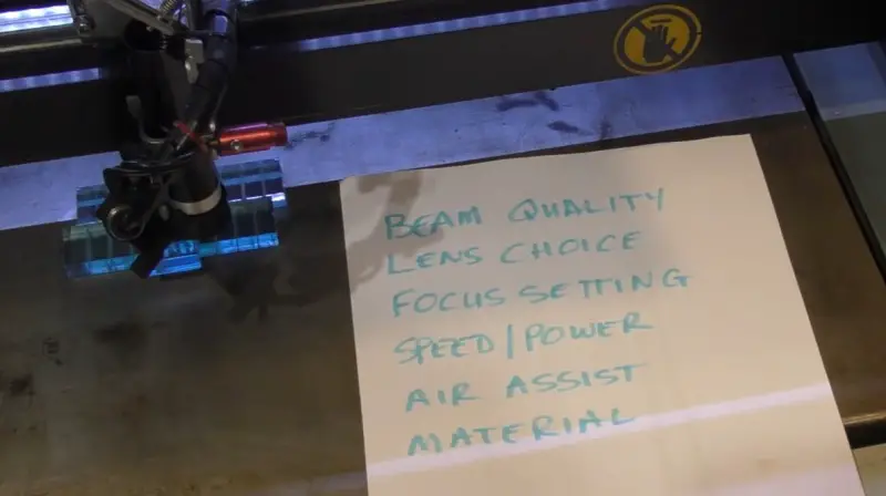
10
00:00:59,490 –> 00:01:03,690
You can’t just set the focal point on the surface, set power and a speed and off you go.
11
00:01:03,690 –> 00:01:15,080
It works, no. Now, one of the first things that new people normally ask me is can you supply me with a set of cutting parameters, please?
12
00:01:15,080 –> 00:01:23,090
Well, I have to be honest and say, no, there is no such thing as a set of cutting parameters.
13
00:01:23,090 –> 00:01:31,970
There are a set of cutting parameters for your machine, but those parameters will not necessarily work on anybody else’s machine.
14
00:01:31,970 –> 00:01:39,020
So if you go to the Thunder Laser website, which is a dot com website, you’ll see that under technical support.
15
00:01:39,020 –> 00:01:40,190
You’ve got downloads.
16
00:01:40,190 –> 00:01:47,270
Now if you scroll down this page, you’ll get to a point where it says thunder laser cutting power and speed parameters for different materials.
17
00:01:47,270 –> 00:01:53,570
And here you’ve got a list of tube powers that are the basic nominal parameters for a tube power.
18
00:01:53,570 –> 00:01:59,000
Let’s just choose this one because my machine is about 80 watts and you’ll see that for an 80 watt tube.
Transcript for Let’s Get Laser Cutting – Laser Cutting Parameters (Cont…)
19
00:01:59,000 –> 00:02:06,470
They say this is a two inch lens for cutting. And this is a two inch lens for engraving. A four inch lens, for cutting.
20
00:02:06,470 –> 00:02:13,370
And they don’t recommend it for engraving. That’s not entirely true because a four inch lens can be very good for 3D engraving
21
00:02:13,370 –> 00:02:18,200
and doing other sorts of engraving because of the soft nature of the burn.
22
00:02:18,200 –> 00:02:25,700
Hopefully, you’ve already learned that from previous engraving sessions. You know, focus is not that important when it comes to engraving.
23
00:02:25,700 –> 00:02:28,790
Focus is very important when it comes to cutting.
24
00:02:28,790 –> 00:02:33,860
The only numbers that you’re going to be able to achieve are the ones that are suitable for your machine.
25
00:02:33,860 –> 00:02:41,720
So I’m afraid you will have to have a notebook and a pencil, and you will have to make a note of things that work for you.
26
00:02:41,720 –> 00:02:42,950
Now within RDWorks,
27
00:02:42,950 –> 00:02:50,450
there is a material library that you can fill in. But of course, you fill that library in and change your tube and it will no longer be any use to you.
28
00:02:50,450 –> 00:03:02,450
So all I’m saying is be very careful about parameters. So cutting is dependent upon many elements, and the most important is the top one: beam quality.
29
00:03:02,450 –> 00:03:07,460
If you don’t have a good Gaussian beam, you’re not going to be able to get a sharp burn.
30
00:03:07,460 –> 00:03:11,390
Now remember, your maximum power might be 70 or 80 percent.
31
00:03:11,390 –> 00:03:15,320
It depends on the current flow that you’re allowed to pass through your tube.
32
00:03:15,320 –> 00:03:18,950
And if your maximum sharp beam looks like this, then everything that
33
00:03:18,950 –> 00:03:23,240
I’m going to tell you today and demonstrate to you today, you will not be able to achieve.
34
00:03:23,240 –> 00:03:27,020
You still need to learn about it because hopefully it will help you identify that you’ve got
35
00:03:27,020 –> 00:03:33,110
a rubbish tube and that you really need to replace your tube with a good quality A-Grade tube.
36
00:03:33,110 –> 00:03:41,840
The next thing that’s most important to you is the choice of lens. I’m very lucky that I have got a wide range of lenses to play with,
37
00:03:41,840 –> 00:03:48,740
and I have done a lot of work comparing the performance of different types of lens.
38
00:03:48,740 –> 00:03:54,500
The X’s is on that table indicate the lenses that I’m going to be able to test.
39
00:03:54,500 –> 00:04:02,000
That basically covers Chinese lenses, American lenses and gallium arsenide lenses, zinc selenide, zinc selenide.
Transcript for Let’s Get Laser Cutting – Laser Cutting Parameters (Cont…)
40
00:04:02,000 –> 00:04:10,580
And we’ve got these four focal lengths and I’ve been testing the lenses both flat side up and flat side down. Meniscus,
41
00:04:10,580 –> 00:04:19,010
flat side down, meniscus flat side up. So there’s a whole range of tests there that cover virtually everything the you are ever likely to encounter.
42
00:04:19,010 –> 00:04:27,350
The first part was all about proving that, hey, there is no such thing as a focal point, so we go through all the lenses there and miss that out.
43
00:04:27,350 –> 00:04:34,790
And then we get to a summary section here now on this table. We asked the question Does the focus vary for different materials?
44
00:04:34,790 –> 00:04:40,820
And there’s a whole range of materials here that I’ve tested and I’ve tested them at different speeds and powers.
45
00:04:40,820 –> 00:04:45,500
So we can see at the top here, that I used a thirty eight point one gallium arsenide plano
46
00:04:45,500 –> 00:04:53,600
convex lens flat side down. The correct way to use a lens and using that lens with these materials.
47
00:04:53,600 –> 00:05:01,310
Here’s the variation in focal distance that I got: 36 to 38, 36 to 39, 37 to 39.
Transcript for Let’s Get Laser Cutting – Laser Cutting Parameters (Cont…)
48
00:05:01,310 –> 00:05:07,940
So the lens focal distance changes with material. Does the focus change with speed?
49
00:05:07,940 –> 00:05:11,870
Well, there’s an answer to the question. Now I’ll let you read that.
50
00:05:11,870 –> 00:05:16,580
And then there’s a third question here does the focus change with power?
51
00:05:16,580 –> 00:05:19,610
There’s another set of data there that you can read.
52
00:05:19,610 –> 00:05:26,810
OK, so this table basically tells you that the intensity focal point, which is not the same as the manufacturer’s focal point,
53
00:05:26,810 –> 00:05:32,360
was defined as that position that achieves the deepest cut the red number.
54
00:05:32,360 –> 00:05:40,370
OK, now my line method and the ramp method that people use for determining the focal point.
55
00:05:40,370 –> 00:05:49,580
It basically finds a completely different intensity focus. The green numbers, which are basically the thinnest line, so minus numbers,
56
00:05:49,580 –> 00:05:56,720
means the focal distance has gone short and plus numbers means the focal distance has gone long.
Transcript for Let’s Get Laser Cutting – Laser Cutting Parameters (Cont…)
57
00:05:56,720 –> 00:06:05,930
Now there’s also another set of data that I derived, which is basically when you set the best depth intensity, i.e. the red numbers.
58
00:06:05,930 –> 00:06:13,600
Here is an idea of the cutting performance by time in milliseconds to reach four or six millimetres. Basically,
59
00:06:13,600 –> 00:06:25,220
it determines the speed of penetration for your lens, for a given, for a given amount of power, and the power that I was using was maximum power.
60
00:06:25,220 –> 00:06:28,130
OK, so all these lenses have got different performances.
61
00:06:28,130 –> 00:06:34,220
And so what we’re really looking here, the best performing lens will be the lens that produces the smallest numbers.
62
00:06:34,220 –> 00:06:40,040
Well, look, most of the time you can see that with tens. eights, eight milliseconds, eight milliseconds.
63
00:06:40,040 –> 00:06:44,420
Some are a lot longer. And here we get eight milliseconds again, 8 8 8.
64
00:06:44,420 –> 00:06:54,740
But look at this one. Not only is it good to six millimetres, to four millimetres, look how it gets to six millimetres.
65
00:06:54,740 –> 00:06:59,390
It gets to six millimetres very quickly in relation to all these others.
66
00:06:59,390 –> 00:07:06,410
Look at them. All right. So this one is obviously the fastest penetrating lens,
67
00:07:06,410 –> 00:07:15,350
and that is the lens that I personally use; a two and a half inch gallium arsenide plano convex flat side down.
68
00:07:15,350 –> 00:07:24,590
And so here’s the test I’ve just been talking about. So look, there’s two millimetres in the background there four, six, eight, 10 millimetres.
69
00:07:24,590 –> 00:07:30,700
So this this particular one, which is a four inch CVD, used
70
00:07:30,700 –> 00:07:43,210
flat side up. Took two four, six, eight, 10, 12, 14, 16, 18, so it took 18 seconds to reach two four six mm.
71
00:07:43,210 –> 00:07:56,230
These nine cuts on here are four millimetres into the material three two one zero and then we’ve got one two three four.
Transcript for Let’s Get Laser Cutting – Laser Cutting Parameters (Cont…)
72
00:07:56,230 –> 00:08:02,110
In other words, I’ve now drawn the focal point out above the manufacturer’s focal point.
73
00:08:02,110 –> 00:08:07,600
We’ve basically got our thinnest line. So if you look here, we’ve got a very thick, going thick line.
74
00:08:07,600 –> 00:08:13,810
We’ve got all this curvature on the top of these. All right. And then look, that one might be the thinnest.
75
00:08:13,810 –> 00:08:16,420
It’s difficult to say, but it’s that one or that one.
76
00:08:16,420 –> 00:08:23,200
One of those two represents the thinnest, and I suspect I must have chosen that one when I looked at it under the microscope because look,
77
00:08:23,200 –> 00:08:28,570
there is a little bit of curvature on the top there, whereas this one has got a nice, crisp corner to it.
78
00:08:28,570 –> 00:08:35,200
But look at the difference between the penetration, the cut penetration here and here.
79
00:08:35,200 –> 00:08:44,260
I mean, these, as it happens, are all about the same. This line drawn across here is five mm depth, just as a reference.
80
00:08:44,260 –> 00:08:49,240
So the important thing is to set the focal point correctly.
81
00:08:49,240 –> 00:08:57,010
What is correct? Well, if you want the deepest cut, it may well be in this instance that you’ve got to set it on the surface.
82
00:08:57,010 –> 00:09:02,590
Zero. Fifty point eight. But if you set it to fifty point eight, you get this effect
83
00:09:02,590 –> 00:09:07,690
on the surface. You get a wide cut mouth, you get a curvature at the input.
84
00:09:07,690 –> 00:09:13,900
Okay, you get a deep cut, but the compromise is you’ve got to suffer a wider line.
85
00:09:13,900 –> 00:09:18,820
If you want the thinnest possible line, then obviously you’re going to have to go maybe one, two,
86
00:09:18,820 –> 00:09:26,590
three or four millimetres above the focal point to get the thinnest possible line for engraving. Or the thinnest possible line
87
00:09:26,590 –> 00:09:34,720
for instance, if you’re doing marquetry where you want the thinnest possible line. You don’t want anything like this if you’re trying to produce very,
88
00:09:34,720 –> 00:09:41,020
very crisp, sharp edges. So you need to go through and study these pictures for your particular lens.
89
00:09:41,020 –> 00:09:48,850
Hang on. This may well be your lens a 50.8 CVD, but you wouldn’t generally use it curve side down.
90
00:09:48,850 –> 00:09:53,290
You’d use it flat side down. So let’s have a look at what flat side down which is your lens.
91
00:09:53,290 –> 00:09:59,650
Let’s just have a look. It must be here. There it is, fifty point eight CVD.
Transcript for Let’s Get Laser Cutting – Laser Cutting Parameters (Cont…)
92
00:09:59,650 –> 00:10:09,460
That’s your lens. Almost certainly. I’ve got a PVD meniscus lens, the correct way and the correct way.
93
00:10:09,460 –> 00:10:16,600
Well, the deepest cut appears to be here, but look at the difference in the line entry width.
94
00:10:16,600 –> 00:10:22,510
OK, the damage that’s caused by the low energy at the outer part of the beam.
95
00:10:22,510 –> 00:10:31,840
Okay, now if you want to use it for engraving, then the sharpest corners are here maybe the thinnest line might be here.
96
00:10:31,840 –> 00:10:34,810
So that’s what I mean about lens choice.
97
00:10:34,810 –> 00:10:43,420
There’s a huge range of cutting effects you get from different lenses and the focus settings, as we’ve just demonstrated.
98
00:10:43,420 –> 00:10:50,560
So it is probably fairly important that you download this document and keep it as a reference.
99
00:10:50,560 –> 00:10:57,700
OK, now speed and power, they both affect the cutting performance,
100
00:10:57,700 –> 00:11:04,840
so we’ll go further into that later on. Because speed and power both affect the focal point.
101
00:11:04,840 –> 00:11:09,190
Not the not the physical focal point that the manufacturer tells you about,
102
00:11:09,190 –> 00:11:13,750
but the focal point of the intensity, which is the bit that we need for cutting.
103
00:11:13,750 –> 00:11:19,780
So Air Assist is a subject that people don’t really understand, but they use.
104
00:11:19,780 –> 00:11:24,490
So we’ll treat Air Assist as a completely separate session, but we shall be using it today.
105
00:11:24,490 –> 00:11:30,960
But I’m not going to go into great detail about air assist. There are materials that cut.
106
00:11:30,960 –> 00:11:41,670
And they generally tend to be organic materials, things like leather, wood card, MDF, plywood and any other natural woods.
107
00:11:41,670 –> 00:11:45,990
Cherry ash, maple, those sorts of things.
108
00:11:45,990 –> 00:11:50,220
You can’t cut glass. You can’t cut slate.
109
00:11:50,220 –> 00:11:55,410
You can’t cut marble or any mineral materials and metals.
110
00:11:55,410 –> 00:11:59,490
You can’t cut any metals. We will be able to mark metals.
Transcript for Let’s Get Laser Cutting – Laser Cutting Parameters (Cont…)
111
00:11:59,490 –> 00:12:04,650
We haven’t tackled that yet, but we will do that as a separate subject. At the end, you could mark metals.
112
00:12:04,650 –> 00:12:11,820
But you have to be very careful about how you mark. Now that big table of test data that you’ve seen, was all performed with this wonderful material.
113
00:12:11,820 –> 00:12:20,700
Acrylic, acrylic is a great material, it’s my best friend when it comes to CO2 laser cutting, because it tells me what’s going on.
114
00:12:20,700 –> 00:12:25,770
I can actually watch exactly what’s going on inside a cut.
115
00:12:25,770 –> 00:12:32,790
I can’t do that with wood. But those results may be just for acrylic.
116
00:12:32,790 –> 00:12:41,730
But acrylic is quite slow at cutting. It’s a difficult material to cut, at a one hundred and sixty degrees C it turns to liquid.
117
00:12:41,730 –> 00:12:48,600
And at 200 degrees C, it turns to steam acrylic steam, basically vapor, acrylic vapour.
118
00:12:48,600 –> 00:12:53,210
That’s how the cutting action happens. You’re evaporating away the material.
119
00:12:53,210 –> 00:12:58,530
Now it’s only happening at 200 degrees C, but when it comes to wood, well,
120
00:12:58,530 –> 00:13:05,310
wood has to evaporate away carbon and carbon doesn’t disappear till over 3000 degrees C.
121
00:13:05,310 –> 00:13:10,950
So you think to yourself, well, hang on 3000 degrees C. It must take a lot longer.
122
00:13:10,950 –> 00:13:14,310
Well, you’re coming back to some of the things that we talked about earlier.
123
00:13:14,310 –> 00:13:18,420
Remember the jelly in the cake? Carbon is like the jelly.
124
00:13:18,420 –> 00:13:22,620
It shakes very easily and accepts energy extremely quickly.
125
00:13:22,620 –> 00:13:27,060
And so it can get up to those sort of high temperatures very, very quickly.
126
00:13:27,060 –> 00:13:30,690
Whereas it technically this stuff is like the cake.
127
00:13:30,690 –> 00:13:35,100
It’s very difficult to shake it to make it do something.
128
00:13:35,100 –> 00:13:39,750
And so consequently, this is quite a difficult material to cut. When you look at that chart.
129
00:13:39,750 –> 00:13:43,140
All the figures in those charts are for acrylic.
130
00:13:43,140 –> 00:13:52,080
But if you want an approximation of what it means for other materials, there are basically two approximations. One, if you’re using MDF,
131
00:13:52,080 –> 00:14:01,350
which has got plastic in it as a binder for wood, then typically it will be about the same sort of speed cutting as acrylic.
132
00:14:01,350 –> 00:14:12,960
Slow. OK, but if you want to cut wood, whether it be plywood or whether it be normal wood, you can assume that about twice as fast.
Transcript for Let’s Get Laser Cutting – Laser Cutting Parameters (Cont…)
133
00:14:12,960 –> 00:14:18,390
But they’re numbers that I have experimented with and found out to be true. When you want to select parameters,
134
00:14:18,390 –> 00:14:28,950
you can use that chart, because you can either use the same numbers for acrylic or you can try and interpret them for wood or MDF.
135
00:14:28,950 –> 00:14:36,540
An Acrylic cut can be fascinating because it teaches so much about what you can’t normally see inside a cut.
136
00:14:36,540 –> 00:14:45,930
Now I’ve got this set to full power, and I’m going to run it at a fairly slow speed, five millimetres a second.
137
00:14:45,930 –> 00:14:54,780
What I want you to watch carefully is the way in which the laser beam goes straight down, except for the last little bit.
138
00:14:54,780 –> 00:14:59,560
OK, the last little bit will be what I call dragging.
139
00:14:59,560 –> 00:15:09,710
It’ll be curved away from the line of the cut. Can you see how the cat is lying backwards?
140
00:15:09,710 –> 00:15:15,400
Now, the piece didn’t fall off and it didn’t fall off because it didn’t cut through.
141
00:15:15,400 –> 00:15:22,310
But let’s just see if we can break it off, which we can. Now there’s the a bottom face of our cut.
142
00:15:22,310 –> 00:15:32,180
This is the material that’s left inside, so you’re going to ask the question, why on earth have we got all this spiky stuff inside?
143
00:15:32,180 –> 00:15:36,930
Well, what you’re seeing there is the power.
144
00:15:36,930 –> 00:15:42,540
It’s absolutely rock solid, steady, but the stepper motor is not.
145
00:15:42,540 –> 00:15:46,770
We’re only running this 5mm a second, and at five millimetres a second.
146
00:15:46,770 –> 00:15:52,140
The stepper motor is going jump, jump, jump, jump, jump like that.
147
00:15:52,140 –> 00:15:58,890
So as it goes fast, we get less cut, and as it stops in between it’s steps.
Transcript for Let’s Get Laser Cutting – Laser Cutting Parameters (Cont…)
148
00:15:58,890 –> 00:16:05,190
We get a deeper cut. So what we’re seeing here is the stepper motor,
149
00:16:05,190 –> 00:16:16,920
creating this sawtooth, not the power. The power is constant, but of course, if we leave the power on for longer, it cuts deeper.
150
00:16:16,920 –> 00:16:22,710
And when we leave it on for less time, it cuts less. But this is the direction of cutting across this way.
151
00:16:22,710 –> 00:16:32,000
And look, all of these are leaning in that direction. We’re getting all sorts of bubbling on the surface here.
152
00:16:32,000 –> 00:16:38,620
Can you see that? That’s the boiling effect that I talk about, that’s the liquid phase.
153
00:16:38,620 –> 00:16:45,190
Because it’s boiling and not fully evaporating, and it’s frozen before it’s had a chance to evaporate.
154
00:16:45,190 –> 00:16:51,310
Now when we get right to the other end of the cut. Here’s our bottom surface and here’s the edge of the material.
155
00:16:51,310 –> 00:16:55,680
Look what’s happened? If we put that up there?
156
00:16:55,680 –> 00:17:03,820
It it’s going to cut onto the surface of the material right at the top edge, but it hasn’t cut right to the bottom.
157
00:17:03,820 –> 00:17:11,560
It hasn’t come out to the bottom. This is what I call drag, you know, we’ve got this much drag in the beam.
158
00:17:11,560 –> 00:17:21,810
Many people will interpret this slope here. As a reflection of the laser beam off the acrylic surface.
159
00:17:21,810 –> 00:17:29,150
I’ve had this argument with people many, many times. So hopefully I’m going to be able to prove to you now,
160
00:17:29,150 –> 00:17:37,130
that there is no reflection off this surface and what you’re seeing here is a strange effect of hot gases scouring this.
161
00:17:37,130 –> 00:17:41,030
You can see the damage from our first cut here, the sawtooth from our first cut.
162
00:17:41,030 –> 00:17:47,210
Well, I’m going to put that on the top. So the next cut is on the bottom and it’s easy for us to see.
163
00:17:47,210 –> 00:17:57,900
So I’m going to stop this mid-cut. But what I want you to do is to watch the drag and then when I stop.
Transcript for Let’s Get Laser Cutting – Laser Cutting Parameters (Cont…)
164
00:17:57,900 –> 00:18:07,830
Watch what happens. Now, sometimes high magnification is good and sometimes it’s a bit of a pain.
165
00:18:07,830 –> 00:18:12,880
In this instance, it’s a little bit of a pain because it’s difficult to show you the angle completely.
166
00:18:12,880 –> 00:18:19,740
So what I’ve done, I’ve set the bottom surface of the material true to the bottom edge of the screen.
167
00:18:19,740 –> 00:18:27,690
This edge here is basically vertical, and there’s the stop edge of the beam.
168
00:18:27,690 –> 00:18:32,460
This is the draggy edge of the beam. So let’s pan up the beam.
169
00:18:32,460 –> 00:18:43,420
So that’s the beam diameter there. And as we go down, look, you can see the beam beginning to drag on the right on the left hand side there.
170
00:18:43,420 –> 00:18:55,520
See the angle? Now, the point I’m really making there is, if the beam was actually reflecting off that curved surface,
171
00:18:55,520 –> 00:19:03,700
that angled surface. When I stopped the beam, it would continue to reflect around that surface.
172
00:19:03,700 –> 00:19:13,060
But it doesn’t. It catches up and does what you expect of a light beam, it travels in a straight line straight down,
173
00:19:13,060 –> 00:19:20,920
which is the way that we’re firing the beam into the material. So that drag cannot be anything to do with reflection.
174
00:19:20,920 –> 00:19:30,700
So the point is, if you cut too fast, you’ll be cutting with hot gases and not necessarily,
175
00:19:30,700 –> 00:19:39,490
with the light beam itself. And if the surface happened to be here like this,
176
00:19:39,490 –> 00:19:47,380
then what happened is you’ll get perforations through the bottom surface of your cut and you’ll think. Hello. what’s going on there?
177
00:19:47,380 –> 00:19:54,010
Well, it’s this effect here. It’s your stepper motor that’s allowing the power to come through the bottom of the cut
178
00:19:54,010 –> 00:19:58,630
and then go back into the cut through the bottom of the cut and back up into the cut.
Transcript for Let’s Get Laser Cutting – Laser Cutting Parameters (Cont…)
179
00:19:58,630 –> 00:20:04,720
So if the cut line is across there, you’ll produce a perforated cut across the bottom.
180
00:20:04,720 –> 00:20:12,220
And the only way that you can overcome that is to slow down, let your beam go straight through.
181
00:20:12,220 –> 00:20:17,830
If you allow enough time, the beam will pierce through all the time, straight.
182
00:20:17,830 –> 00:20:22,000
Previously, I was running this at five millimetres a second.
183
00:20:22,000 –> 00:20:38,440
I’m now going to run it at three millimetres a second. Yes, it’s nearly upright, but not quite. As I said to you,
184
00:20:38,440 –> 00:20:47,440
this is acrylic. It melts at 160 degrees C and it evaporates at 200 degrees C.
185
00:20:47,440 –> 00:20:56,750
Now what I want you to do this time is to watch the cut as it traverses along and look just behind the cut itself,
186
00:20:56,750 –> 00:21:06,080
and you’ll see a rather strange effect taking place.
187
00:21:06,080 –> 00:21:14,810
Specifically at the bottom there, can you see that little bit of what looks like drag. It’s not drag.
188
00:21:14,810 –> 00:21:21,080
That’s actually the liquid phase of the material. Bearing in mind,
189
00:21:21,080 –> 00:21:28,460
this stepper motor is pulsing. It’s stepping across and producing all sorts of weird pulses.
190
00:21:28,460 –> 00:21:35,190
Why don’t we have?, those pulses
191
00:21:35,190 –> 00:21:39,970
on the surface of our cut? Look, it’s completely smooth.
192
00:21:39,970 –> 00:21:51,020
And that’s because the liquid phase of the material has settled on the wall and smoothed all the pulses out.
193
00:21:51,020 –> 00:21:58,630
Just like the surface of a piece of water. So the liquid phase is the thing that causes that lovely, smooth finish.
Transcript for Let’s Get Laser Cutting – Laser Cutting Parameters (Cont…)
194
00:21:58,630 –> 00:22:09,940
This is extruded acrylic. It’s very easy to get that effect on extruded acrylic and more difficult to get it on cast acrylic.
195
00:22:09,940 –> 00:22:16,210
So there we go. We’ve shown you that we can cut through a piece of material with an upright cut,
196
00:22:16,210 –> 00:22:21,010
if we do it slow enough. Here we’ve got a piece of 10 millimetre thick plywood.
197
00:22:21,010 –> 00:22:24,520
I should be able to cut this at twice the speed that I can
198
00:22:24,520 –> 00:22:30,650
acrylic. It’s the same thickness, same lens, same settings.
199
00:22:30,650 –> 00:22:36,530
So I’m going to run this at six millimetres a second, and we’ll see what happens.
200
00:22:36,530 –> 00:23:00,000
I’m going to have to turn some extraction on. And I know that it’s cutting through because the smoke is coming out the bottom.
201
00:23:00,000 –> 00:23:03,720
Well, it’s cut through, but it looks a bit of a mess on the bottom, doesn’t it?
202
00:23:03,720 –> 00:23:09,090
Well, that’s because of the reflection off of this steel surface.
203
00:23:09,090 –> 00:23:20,530
This is metal. Remember, it’s a mirror. And the problem is, I’ve got that mirror too close to the underneath of that material.
204
00:23:20,530 –> 00:23:25,480
So first of all, let’s demonstrate this to you. The same settings.
205
00:23:25,480 –> 00:23:36,190
But we now lift it off the deck by 25mm as opposed to 10mm.
206
00:23:36,190 –> 00:23:51,980
You can see lots of smoke coming out at the bottom, which is good. That means we’re blowing air out through the bottom of the cut.
207
00:23:51,980 –> 00:23:59,000
And this time. Pretty clean, just a little hint of something there.
Transcript for Let’s Get Laser Cutting – Laser Cutting Parameters (Cont…)
208
00:23:59,000 –> 00:24:04,730
OK. And. It’s come out.
209
00:24:04,730 –> 00:24:09,850
Look, we’ll run it slightly faster. Instead of,
210
00:24:09,850 –> 00:24:17,480
instead of six millimetres a second, we’ll run it at 8mm a second.
211
00:24:17,480 –> 00:24:31,040
Yeah, there’s some smoke coming out the bottom. We’ve got a lot more debris out the top here.
212
00:24:31,040 –> 00:24:39,500
The cut is black. The other thing to note is that cut at the bottom looks like a good cut, it’s through.
213
00:24:39,500 –> 00:24:47,180
So why didn’t it fall out? Well, the reason it didn’t fall out is, if we look just here.
214
00:24:47,180 –> 00:24:56,960
You’ll see that there’s a bit missing. The cut didn’t complete. That’s beam drag, because the top of the cut is complete all the way round.
215
00:24:56,960 –> 00:25:02,840
This is the start point. So it started here, went round and finished up here.
216
00:25:02,840 –> 00:25:11,620
But when it got to there, the bottom of the cut is dragging. Sometimes you can use that to your advantage.
217
00:25:11,620 –> 00:25:16,750
It’s almost like an automatic bridge, if you want to stop the pieces from falling out.
218
00:25:16,750 –> 00:25:19,510
I mean, it will fall out very easily. All right.
219
00:25:19,510 –> 00:25:23,350
But the reason I’m not going to push out for the moment is because I want you to look at something else.
220
00:25:23,350 –> 00:25:29,400
And that’s the difference in the cut width at the bottom here.
221
00:25:29,400 –> 00:25:36,810
And the cut width the top. OK, I haven’t necessarily got this set to the correct focus. We’ll reset this focus
222
00:25:36,810 –> 00:25:42,510
in a minute and we’ll change the relationship between the top and the bottom.
223
00:25:42,510 –> 00:25:49,530
We’re relying on a through cut to allow the smoke to come out of the bottom of the cut.
224
00:25:49,530 –> 00:25:56,660
You may well remember a couple of sessions ago, how I said to you that the very first part of a cut,
225
00:25:56,660 –> 00:26:02,300
is like a drill hole. It’s piercing through, and that is what you’re seeing here,
Transcript for Let’s Get Laser Cutting – Laser Cutting Parameters (Cont…)
226
00:26:02,300 –> 00:26:10,460
you’re seeing the fumes coming upwards and spreading across your material because there is nowhere for those fumes to go.
227
00:26:10,460 –> 00:26:18,650
Only when we get the cut established along here do we have a gap out the bottom of the cut for the fumes to escape.
228
00:26:18,650 –> 00:26:23,620
I can improve things slightly by increasing
229
00:26:23,620 –> 00:26:36,170
the air assist. Now at the moment, my air assist is turned off nearly, so I’ll run the same program again with full air assist on.
230
00:26:36,170 –> 00:26:47,060
And you can see now the smoke pouring out the bottom. ok, because I’m blowing it through the cut.
231
00:26:47,060 –> 00:26:51,180
And now, two things you’ll notice.
232
00:26:51,180 –> 00:26:59,670
Number one, it’s a lot cleaner around the edge of the cat because I’m not allowing these fumes to settle on the top of the cut.
233
00:26:59,670 –> 00:27:03,690
They’re being blown out the bottom of the cut. Let’s just turn over.
234
00:27:03,690 –> 00:27:14,100
Look how the air assist has affected cut drag. We’ve improved the cutting efficiency with the air assist to the point where it’s nearly disappeared.
235
00:27:14,100 –> 00:27:20,490
There’s still not what I call a proper cut, because the bottom is not the same as the top.
236
00:27:20,490 –> 00:27:24,210
We’re looking for a parallel cut to be the ideal cut.
237
00:27:24,210 –> 00:27:31,440
Now, the reason why it’s not parallel at the moment is because I haven’t got my focus set. But these pieces, they’re dropping out nicely.
238
00:27:31,440 –> 00:27:36,630
One of the ways you can tell whether or not your cut is good. Is to have a piece of kitchen towel handy.
239
00:27:36,630 –> 00:27:46,090
And look, if you can do this with your kitchen towel. And you get virtually no charring on there.
240
00:27:46,090 –> 00:27:54,430
Then you got you’ve got a pretty good cut. I’m now going to carry out a little focus test on this machine using an automatic program that I’ve developed.
241
00:27:54,430 –> 00:28:00,310
Now you can do the same sort of thing by using a gauge like this and doing it manually.
Transcript for Let’s Get Laser Cutting – Laser Cutting Parameters (Cont…)
242
00:28:00,310 –> 00:28:05,780
So I’m going to set this lens specifically,
243
00:28:05,780 –> 00:28:28,550
low, and at the moment, that’s sat on three millimetres.
244
00:28:28,550 –> 00:28:33,200
OK, so remember, I set the first line up to three millimetres, three, four,
245
00:28:33,200 –> 00:28:39,040
I really ought to be setting this up to five millimetres for the best focus.
246
00:28:39,040 –> 00:28:51,140
5mm. So there’s a maximum allowable milliamps that you can use on your machine. Set that to the maximum that you can when you’re doing cutting.
247
00:28:51,140 –> 00:29:02,310
We’ll run this at 10 millimetres a second and see what we get.
248
00:29:02,310 –> 00:29:11,490
We’re getting a pretty clean cut on top here, except where we enter. As I said, you’ll always tend to get that splash there because of the volcano effect.
249
00:29:11,490 –> 00:29:19,050
We’ve got a slightly thinner, cleaner line now. Let’s take a look at what we’ve got underneath. Well underneath,
250
00:29:19,050 –> 00:29:25,740
we’ve got a thinner line than we had before probably. Look, it’s just that little teeny weeny corner just there, that’s stopping
251
00:29:25,740 –> 00:29:31,290
it from popping out. We can hardly tell the difference between top and bottom. So we’ve got no scorching on the bottom.
252
00:29:31,290 –> 00:29:36,690
We can see where the bottom is because look, there’s our there’s a little teeny weeny pit there that was holding it in.
253
00:29:36,690 –> 00:29:48,420
So that’s the bottom. And that’s the top. That’s a nice, clean cut. Something that we’ve got to keep an eye on, is the squareness of our cut.
254
00:29:48,420 –> 00:29:55,320
OK. To make sure that we’ve got our beam set correctly. As I said to you,
255
00:29:55,320 –> 00:30:02,820
many people will tell you that you’ll get an angle cut because of the way in which the laser beam tends to come out
Transcript for Let’s Get Laser Cutting – Laser Cutting Parameters (Cont…)
256
00:30:02,820 –> 00:30:10,810
in a cone underneath the focal point. I’ve demonstrated that to you a couple of sessions ago when we spoke about lenses.
257
00:30:10,810 –> 00:30:17,980
Any angle that you get on your cut is nothing to do with the lens itself, it’s all to do with the direction of the beam of light.
258
00:30:17,980 –> 00:30:24,820
If the light is not passing through the axis of the lens, it will veer off at an angle and produce an angle cut.
259
00:30:24,820 –> 00:30:32,530
Now we’ve also shown you that this surface here, this metal surface at the back, which is steel, can reflect.
260
00:30:32,530 –> 00:30:42,760
It’s about 60 percent reflective even in this fairly cruddy state, and it will have an effect on the back surface if your work if you’re not careful.
261
00:30:42,760 –> 00:30:47,770
Raise it up. Allow it to dissipate more so that there’s less intense energy.
262
00:30:47,770 –> 00:30:54,370
And here you can see we’ve got hardly any effect of, well we’ve got zero effect of reflection here for two reasons.
263
00:30:54,370 –> 00:30:59,960
Number one, we’ve lifted it up and number two, we’re running faster. Your parameters,
264
00:30:59,960 –> 00:31:04,270
will be the ones for your machine. I can’t give you any of those parameters.
265
00:31:04,270 –> 00:31:10,480
All I can give you is basic rules that you should follow to obtain your parameters.
266
00:31:10,480 –> 00:31:16,330
Run the machine as fast as you can. Run the machine until your material drops out.
267
00:31:16,330 –> 00:31:20,380
Use something like this a square test 25 mm square.
268
00:31:20,380 –> 00:31:28,360
Run it too fast and the material won’t fall out. Run it a little bit slower and slower and slower until the material falls out.
269
00:31:28,360 –> 00:31:31,480
Make sure that just before the material falls out,
270
00:31:31,480 –> 00:31:37,570
you’ve got a nice cut at the bottom and that your smoke is passing right through the material and coming out the bottom.
271
00:31:37,570 –> 00:31:42,730
Look at the condensed tar that came out at the bottom of my wood there.
272
00:31:42,730 –> 00:31:49,820
A little bit of acetone. And it wipes off. Don’t leave it on because if you leave it on.
273
00:31:49,820 –> 00:31:55,330
Look, this is some stuff that I happened to leave on, and it sort of somehow corrodes into the surface.
Transcript for Let’s Get Laser Cutting – Laser Cutting Parameters (Cont…)
274
00:31:55,330 –> 00:32:13,020
The only way I’m going to get this off is with something like a 3M pad or a rotary sanding disk.
275
00:32:13,020 –> 00:32:23,300
I can remove this, we got a solid bar bed.
276
00:32:23,300 –> 00:32:28,450
And I’ve got one of these horrible things that I use occasionally.
277
00:32:28,450 –> 00:32:35,440
Piece of honeycomb. Most people on their machines will have honeycomb, but hey, look at this, for example,
278
00:32:35,440 –> 00:32:41,350
can you see that piece of, can you see that little teeny tiny piece of acrylic wedged in there?
279
00:32:41,350 –> 00:32:43,240
Hmm, that’s pretty dangerous.
280
00:32:43,240 –> 00:32:53,540
It’s called honeycomb for good reason, because that’s what it looks like. In the same way that if you open up a bees nest, you’re going to get stung.
281
00:32:53,540 –> 00:32:56,320
This is almost as dangerous.
282
00:32:56,320 –> 00:33:05,690
This is a very convenient point to stop this session because the beginning of the next session, we’re going to have to talk about this stuff.
283
00:33:05,690 –> 00:33:08,830
Now, look, I’ve had this for six years.
284
00:33:08,830 –> 00:33:16,990
Yeah, it’s a little bit worn, but it’s not terrible in relation to what some people’s honeycomb looks like after a few months.
285
00:33:16,990 –> 00:33:21,670
That’s because I have a love hate relationship with this stuff.
286
00:33:21,670 –> 00:33:27,400
And so on that cliff-hanger, we’ll save that story till the next session.
Transcript for Let’s Get Laser Cutting – Laser Cutting Parameters
 Skip to content