Skip to content
 All tests were designed and conducted by Russ Sadler: August 2021
Table of Contents
Introduction
What is the best laser lens to use: I looked back to see when my obsession to understand how a laser beam and lens interact to produce a cutting effect. It surprised me to find that this love affair started in August 2018. Three years on and I realize I have been forced to dive ( well, paddle ankle deep), into subjects my engineering career never prepared me for.
Acquiring a few skeletal rudiments of physics, chemistry, material science and optics has decreased my ignorance by about 1%. My innate talent for observing things that don’t make sense, combined with the scepticism encoded in my DNA, have been drivers that prevented me walking away from the energy density puzzle I encountered whilst testing the few lenses I had at the time.
The ensuing three years have thrown more and more incongruities into the mix. I regularly observed a fluid focal point that can be varied with speed, power and material. I was even more perplexed by the ability of a short focus lens to cut a parallel path through thick material when the conventional model of diverging rays and reduced energy density below the focal point predicted this to be impossible. When the impossible was happening before my eyes and was repeatable, there had to be problem somewhere.
My abundant ignorance and tenacious curiosity are powerful problem solving tools. However, I am not that stupid as to try and reinvent the wheel and so I have diligently sought advice from academia, the optics industry, laser specialists and of course, www.
The lack of any credible or applicable prior knowledge seemed unbelievable considering laser technology within industry has been around since 1965. So with nothing more than a shed, two grey cells and a Chinese laser machine, I had to set about inventing simple experimental methods to track down the root cause of all my observed anomalies. My RDWorks Learning Lab series on YouTube documents my many failures along with gaining many positive but seemingly disconnected pieces of the puzzle.
A few weeks ago I had a light bulb moment that allowed me to connect those many puzzle pieces in a coherent manner and I could clearly visualize how the cutting mechanism was happening. However, there was a ripple effect to my vision that joined many other pieces and raised some serious questions.
BIG DOUBT!!!! What I was visualizing did not accord with conventional geometrical lens theory that began with Euclid in about 250BC………….but then again, Euclid had no Chinese laser machines to colour his thinking.
I had to ask myself. “Does this mean that either I or lens theory is wrong? The answer to both questions turns out to be “No”.
Lenses of all sorts are designed in accordance with well proven optical rules. Those rules include the assumption that all light rays are essentially equal and is true for all types of imaging optics as used in telescopes, microscopes, projectors and cameras. Lenses have to be made according to those rules to ensure design predictability.
There is NOTHING wrong with the design or manufacture of lenses. However, there appears to be a mistaken belief that a laser beam will react to a lens in the same way as normal light. That conceptual blind spot is the source of all my observed anomalies. A laser machine is NOT an imaging system.
Russ Sadler – August 2021
My explanation seems simple now that it is decoded but there are several key pieces of science to be understood. They include the peculiar non-uniform INTENSITY of light within a laser beam and an understanding of the mechanism by which light energy transfers to mechanical energy at the molecular level in materials.
Put simply, the more INTENSE the light the faster that mechanical energy transfer will happen and the faster the laser beam will damage material. However, the centre of the beam is more intense than the outer part of the beam so material damage will not be uniform.
Russ Sadler – August 2021
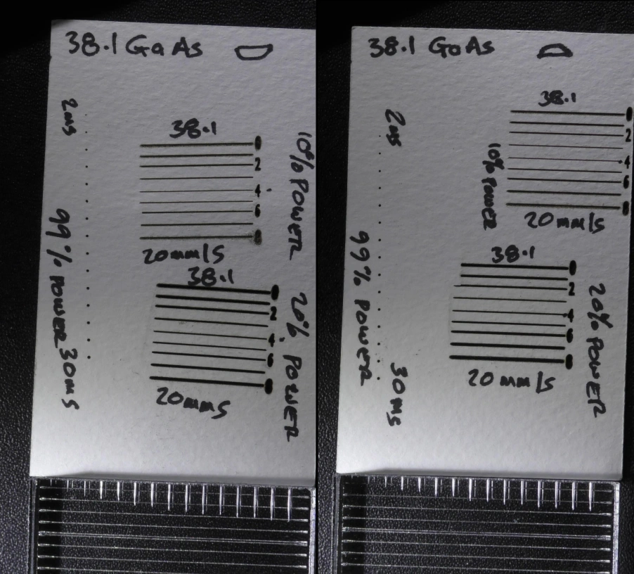
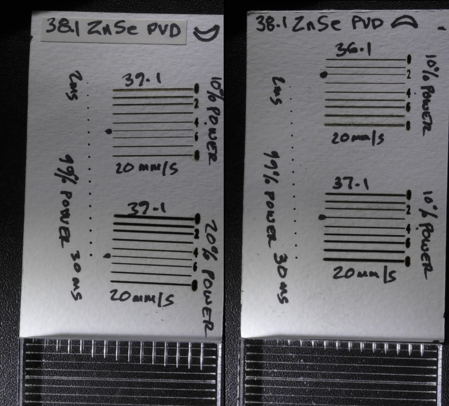
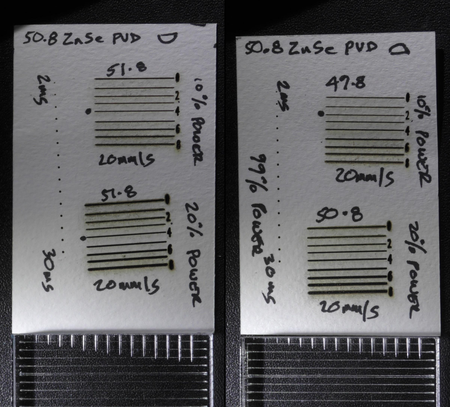
Another vital part of the cutting mechanism is the concept of spherical aberration. For our Chinese laser machines we are limited to just two lens forms. One is plano convex and the other is positive meniscus. Both have lens surfaces that are spherical. And no matter how perfect the geometry there will always be degree of this error.
The lens is designed to be used the “right way round” with the convex face away from the material. This is designed to minimise aberration and increase the convergence of light to a single focal point.
How these concepts link together is explained in the following video:
The key takeaways for what is the best laser lens to use are:-
- A lens needs significant aberration to produce a deep cutting action, hence a Plano Convex lens used “the wrong way” is generally better than the manufacturers recommended way.
- The reduced aberration in a meniscus lens is generally good for engraving and less efficient at cutting.
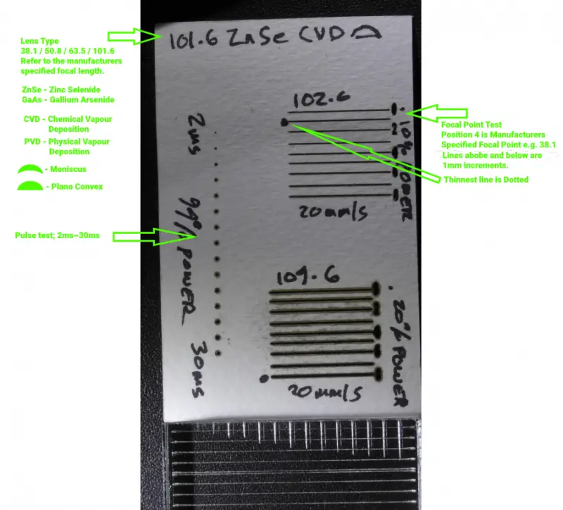
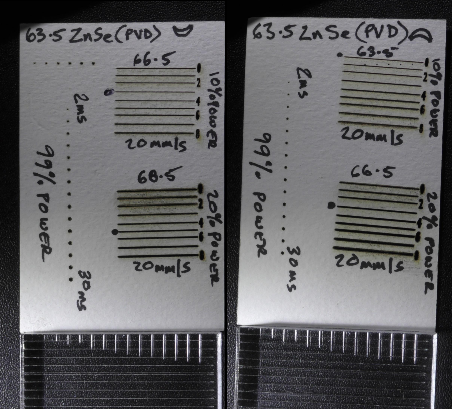
- There is NO fixed focal point. That is a normal light concept and is not applicable here. Instead there is an aggregation of INTENSITY that is NOT a single point but is a zone. There will be a position where speed, power and material damage threshold will balance against intensity to produce the smallest damage zone. This appears to be a focus but it is an INTENSITY focus and NOT a focal point of light rays. You will see this in EVERY picture that follows:
- The line of dots is a full power beam at increasing exposure times. If this was a REAL focal point (or SPOT size) then all dots would be the same size.
- Equally, if the focal point was the thinnest line, there are two things to note.
- Why is the thinnest line not the same for both line tests? The single fixed focal point concept should mean the focus is the same for both tests.
- I have noted the position of the INTENSITY focus on the top test line. Speed is always 20mm/s but the two tests were just 10% different in power. Why are the lines not at the same focus point? This could not happen if a FIXED focal point system were operating. I know that the DESIGNED fixed focal point is still there but the laser beam is ignoring it.
In each picture that follows, on the bottom, you will see an acrylic block that has been set with its surface at the manufactured focal point. The beam has then pierced the block for exposure times starting at 2ms on the top, incrementing by 2ms until reaching the last 30ms penetration. This image shows the rate of material damage and the diameter of the damage. The lines in the background are 2mm spacing. This shows the inaccuracy of claiming that the “wrong way” is bad.

TABLE OF LENSES THAT I HAVE CHARACTERISED
| Focal Length (mm) | P/C Flat Down ZnSe PVD | P/C Flat Up ZnSe PVD | Men Flat Down ZnSe PVD | Men Flat Up ZnSe PVD | P/C Flat Down ZnSe CVD | P/C Flat Up ZnSe CVD | Men Flat Down ZnSe CVD | Men Flat Up ZnSe CVD | P/C Flat Down GaAs | P/C Flat Up GaAs | Men Flat Down GaAs | Men Flat Up GaAs |
|---|---|---|---|---|---|---|---|---|---|---|---|---|
| 38.1 | X | X | X | X | X | X | X | X | ||||
| 50.8 | X | X | X | X | X | X | X | X | ||||
| 63.5 | X | X | X | X | X | X | X | X | ||||
| 101.6 | X | X | X | X | X | X | X | X | X | X |
The card used in the following tests is 0.3mm thick artists water colour parchment. It is almost pure wood pulp and has a wide tonal range. I.e. it displays from very pale brown to carbon black and is able to display a range of intensities.
The Effect of Speed and Power on the Focal Point for Different Materials
- Lens Used for the following table is the 38.1mm / 1.5″ GaAs Plano Convex lens, (flat Side down)
- The Manufacturers Stated Working Range from Focal Point = +/-1.9mm
- Manufacturers Stated Focal Spot Size = 0.05mm
- Focus Position (mm) has been determined by using the test procedures as shown in the previous photos and choosing the thinnest line for each speed and power combination.
| Material | Speed (mm/s) | Power % (of 70W) | Thinnest Line (mm) | Focus Pos’n (mm) | Speed (mm/s) | Power % (of 70W) | Thinnest Line (mm) | Focus Pos’n (mm) | Speed (mm/s) | Power % (of 70W) | Thinnest Line (mm) | Focus Pos’n (mm) |
|---|---|---|---|---|---|---|---|---|---|---|---|---|
| Anodised Aluminium | 400 | 95 | 0.18 | 36 | 10 | 95 | 0.25 | 36 | 10 | 10 | 0.07 | 37 |
| Ceramic Tile | 400 | 95 | 0.05 | 37 | 10 | 95 | 0.4 | 39 | 10 | 10 | 0.25 | 37 |
| Glass | 400 | 95 | 0.3 | 37 | 10 | 95 | 1.2 | 39 | 10 | 10 | 0.05 | 37 |
| PET | 400 | 95 | 0.5 | 38 | 10 | 95 | 0.6 | 38 | 10 | 10 | 0.5 | 39 |
| Slate | 400 | 95 | 0.35 | 36 | 10 | 95 | 0.8 | 37 | 10 | 10 | 0.15 | 38 |
| Baltic Birch PLY | 400 | 95 | 0.2 | 37 | 10 | 95 | 0.55 | 38 | 10 | 10 | 0.2 | 39 |
| Leather Hide | 400 | 95 | 0.37 | 38 | 10 | 95 | 0.75 | 37 | 10 | 10 | 0.4 | 38 |
| Marine PLY | 400 | 95 | 0.35 | 37 | 10 | 95 | 0.55 | 37 | 10 | 10 | 0.3 | 39 |
| Cast Acrylic Translucent White | 400 | 95 | 0.25 | 37 | 10 | 95 | 0.45 | 38 | 10 | 10 | 0.15 | 38 |
| Cast Acrylic Clear | 400 | 95 | 0.26 | 37 | 10 | 95 | 0.35 | 36 | 10 | 10 | 0.17 | 38 |
| Extruded Acrylic Clear | 400 | 95 | 0.17 | 37 | 10 | 95 | 0.3 | 37 | 10 | 10 | 0.17 | 38 |
| HDF | 400 | 95 | 0.2 | 37 | 10 | 95 | 0.6 | 38 | 10 | 10 | 0.25 | 38 |
| MDF | 400 | 95 | 0.2 | 37 | 10 | 95 | 0.5 | 37 | 10 | 10 | 0.2 | 39 |
| Thin White Card With Kaolin Fill | 400 | 95 | 0.15 | 38 | 10 | 95 | 0.25 | 39 | 10 | 10 | 0.25 | 39 |
| Beer Mat Card (Pure Wood Pulp) | 400 | 95 | 0.3 | 37 | 10 | 95 | 0.5 | 37 | 10 | 10 | 0.2 | 38 |
- What is the range of line thicknesses at the Focal Point?
- 400mm/s Speed & Power 95% = 0.05~0.5mm
- 10mm/s Speed & Power 95% = 0.25~1.2mm
- 10mm/s Speed & Power 10% = 0.07~0.4mm
- What is the range of the measured Focal Points for Different Materials?
- 400mm/s Speed & Power 95% = 36~38mm
- 10mm/s Speed & Power 95% = 36~39mm
- 10mm/s Speed & Power 10% = 37~39mm
Does Focus change with Speed?
- 400mm/s is engraving speed and 10mm/s is a cutting speed
- The red numbers are a reference focal distance for the material.
- The Green numbers show a change of focus with speed.
- 70% of results change with Speed
| Material | Speed (mm/s) | Power % (of 70W) | Thinnest Line (mm) | Focus Pos’n (mm) | Speed (mm/s) | Power % (of 70W) | Thinnest Line (mm) | Focus Pos’n (mm) | Speed (mm/s) | Power % (of 70W) | Thinnest Line (mm) | Focus Pos’n (mm) |
|---|---|---|---|---|---|---|---|---|---|---|---|---|
| Anodised Aluminium | 400 | 95 | 0.18 | 36 | 10 | 95 | 0.25 | 36 | 10 | 10 | 0.07 | 37 |
| Ceramic Tile | 400 | 95 | 0.05 | 37 | 10 | 95 | 0.4 | 39 | 10 | 10 | 0.25 | 37 |
| Glass | 400 | 95 | 0.3 | 37 | 10 | 95 | 1.2 | 39 | 10 | 10 | 0.05 | 37 |
| PET | 400 | 95 | 0.5 | 38 | 10 | 95 | 0.6 | 38 | 10 | 10 | 0.5 | 39 |
| Slate | 400 | 95 | 0.35 | 36 | 10 | 95 | 0.8 | 37 | 10 | 10 | 0.15 | 38 |
| Baltic Birch PLY | 400 | 95 | 0.2 | 37 | 10 | 95 | 0.55 | 38 | 10 | 10 | 0.2 | 39 |
| Leather Hide | 400 | 95 | 0.37 | 38 | 10 | 95 | 0.75 | 37 | 10 | 10 | 0.4 | 38 |
| Marine PLY | 400 | 95 | 0.35 | 37 | 10 | 95 | 0.55 | 37 | 10 | 10 | 0.3 | 39 |
| Cast Acrylic Translucent White | 400 | 95 | 0.25 | 37 | 10 | 95 | 0.45 | 38 | 10 | 10 | 0.15 | 38 |
| Cast Acrylic Clear | 400 | 95 | 0.26 | 37 | 10 | 95 | 0.35 | 36 | 10 | 10 | 0.17 | 38 |
| Extruded Acrylic Clear | 400 | 95 | 0.17 | 37 | 10 | 95 | 0.3 | 37 | 10 | 10 | 0.17 | 38 |
| HDF | 400 | 95 | 0.2 | 37 | 10 | 95 | 0.6 | 38 | 10 | 10 | 0.25 | 38 |
| MDF | 400 | 95 | 0.2 | 37 | 10 | 95 | 0.5 | 37 | 10 | 10 | 0.2 | 39 |
| Thin White Card With Kaolin Fill | 400 | 95 | 0.15 | 38 | 10 | 95 | 0.25 | 39 | 10 | 10 | 0.25 | 39 |
| Beer Mat Card (Pure Wood Pulp) | 400 | 95 | 0.3 | 37 | 10 | 95 | 0.5 | 37 | 10 | 10 | 0.2 | 38 |
Does Focus change with Power?
- 400mm/s is engraving speed and 10mm/s is a cutting speed
- The blue numbers (or italic numbers) are a reference focal distance for the material at 10% power.
- The red numbers (or bold numbers)show a change of focus with power.
- 80% of results change with Power.
| Material | Speed (mm/s) | Power % (of 70W) | Thinnest Line (mm) | Focus Pos’n (mm) | Speed (mm/s) | Power % (of 70W) | Thinnest Line (mm) | Focus Pos’n (mm) | Speed (mm/s) | Power % (of 70W) | Thinnest Line (mm) | Focus Pos’n (mm) |
|---|---|---|---|---|---|---|---|---|---|---|---|---|
| Anodised Aluminium | 400 | 95 | 0.18 | 36 | 10 | 95 | 0.25 | 36 | 10 | 10 | 0.07 | 37 |
| Ceramic Tile | 400 | 95 | 0.05 | 37 | 10 | 95 | 0.4 | 39 | 10 | 10 | 0.25 | 37 |
| Glass | 400 | 95 | 0.3 | 37 | 10 | 95 | 1.2 | 39 | 10 | 10 | 0.05 | 37 |
| PET | 400 | 95 | 0.5 | 38 | 10 | 95 | 0.6 | 38 | 10 | 10 | 0.5 | 39 |
| Slate | 400 | 95 | 0.35 | 36 | 10 | 95 | 0.8 | 37 | 10 | 10 | 0.15 | 38 |
| Baltic Birch PLY | 400 | 95 | 0.2 | 37 | 10 | 95 | 0.55 | 38 | 10 | 10 | 0.2 | 39 |
| Leather Hide | 400 | 95 | 0.37 | 38 | 10 | 95 | 0.75 | 37 | 10 | 10 | 0.4 | 38 |
| Marine PLY | 400 | 95 | 0.35 | 37 | 10 | 95 | 0.55 | 37 | 10 | 10 | 0.3 | 39 |
| Cast Acrylic Translucent White | 400 | 95 | 0.25 | 37 | 10 | 95 | 0.45 | 38 | 10 | 10 | 0.15 | 38 |
| Cast Acrylic Clear | 400 | 95 | 0.26 | 37 | 10 | 95 | 0.35 | 36 | 10 | 10 | 0.17 | 38 |
| Extruded Acrylic Clear | 400 | 95 | 0.17 | 37 | 10 | 95 | 0.3 | 37 | 10 | 10 | 0.17 | 38 |
| HDF | 400 | 95 | 0.2 | 37 | 10 | 95 | 0.6 | 38 | 10 | 10 | 0.25 | 38 |
| MDF | 400 | 95 | 0.2 | 37 | 10 | 95 | 0.5 | 37 | 10 | 10 | 0.2 | 39 |
| Thin White Card With Kaolin Fill | 400 | 95 | 0.15 | 38 | 10 | 95 | 0.25 | 39 | 10 | 10 | 0.25 | 39 |
| Beer Mat Card (Pure Wood Pulp) | 400 | 95 | 0.3 | 37 | 10 | 95 | 0.5 | 37 | 10 | 10 | 0.2 | 38 |
Why is the Focal Point changing with Power & Speed?
These are differences of INTENSITY focal points from the quoted LIGHT RAY focal points.
- The INTENSITY focal point was defined as that position that achieved the deepest cut (red numbers/bold numbers).
- My line method of determining focus and the ramp method are finding a completely different intensity focus (green numbers/italic numbers) .
- Example for a 101.6mm specified focal point -4 = 97.6mm and 5 = 106.6mm
| Focal Length (mm) | P/C Flat Down ZnSe PVD | P/C Flat Up ZnSe PVD | Men Flat Down ZnSe PVD | Men Flat Up ZnSe PVD | P/C Flat Down ZnSe CVD | P/C Flat Up ZnSe CVD | Men Flat Down ZnSe CVD | Men Flat Up ZnSe CVD | P/C Flat Down GaAs | P/C Flat Up GaAs | Men Flat Down GaAs | Men Flat Up GaAs |
|---|---|---|---|---|---|---|---|---|---|---|---|---|
| 38.1 | -4 -1 | 1 1 | -2 0 | 0 1 | -3 -1 | 0 2 | -1 0 | -1 0 | ||||
| 50.8 | -5 -3 | -1 1 | -3 0 | -2 0 | -4 -2 | -4 -2 | ||||||
| 63.5 | -1 2 | 1 4 | -1 2 | -1 4 | 0 3 | 0 3 | -7 -3 | -3 0 | ||||
| 101.6 | -2 0 | -2 0 | 0 4 | 2 4 | -4 2 | -4 0 | -3 4 | 0 4 | -2 0 | -2 0 |
Notes:
- These values are for acrylic, 70 watts power and a speed of 20mm/s.
- If the speed, power or material changes then these values will also change.
- The majority of RED/BOLD numbers are negative and begins to explain why it is claimed that for deeper cutting you should drop the focal point into material by 1/3 thickness. Doing so makes the mouth of the cut very tapered and wide. Examine the following data and images and you will see that there is no predictable focus where this depth gain can be achieved. Most of the time, if you use the 1/3 advice then you will achieve SHALLOWER cutting.
- PRO TIP: My advice is to run several 25mm test squares with material, speed and power you plan to use to determine optimum cutting parameters.
Using the Depth Intensity Focus to Measure Cutting Performance
When set to the best DEPTH INTENSITY focus, here is an idea of cutting performance by the time in milliseconds taken to reach 4mm/6mm depth.
| Focal Length (mm) | P/C Flat Down ZnSe PVD | P/C Flat Up ZnSe PVD | Men Flat Down ZnSe PVD | Men Flat Up ZnSe PVD | P/C Flat Down ZnSe CVD | P/C Flat Up ZnSe CVD | Men Flat Down ZnSe CVD | Men Flat Up ZnSe CVD | P/C Flat Down GaAs | P/C Flat Up GaAs | Men Flat Down GaAs | Men Flat Up GaAs |
|---|---|---|---|---|---|---|---|---|---|---|---|---|
| 38.1 | 12/22 | 10/22 | 8/22 | 8/14 | 18/30 | 10/22 | 8/18 | 12/22 | ||||
| 50.8 | 10/18 | 8/18 | 8/16 | 8/16 | 8/16 | 8/16 | ||||||
| 63.5 | 10/18 | 8/16 | 10/18 | 10/18 | 6/12 | 8/16 | 8/16 | 8/16 | ||||
| 101.6 | 10/22 | 12/22 | 10/20 | 10/20 | 12/22 | 12/22 | 10/22 | 16/24 | 10/18 | 10/18 |
Cutting Performance of Different Lenses at their Measured Depth Intensity Focal Point
Conclusion
The manufacturers data for lenses is applicable to the imaging optics as used in microscopes, cameras , projectors and telescopes. Our laser machines are not pieces of IMAGING equipment and the test results in this document clearly demonstrate that the concept of a FIXED focal point is not applicable to lenses when used with the non-uniform intensity light found in a laser beam. In general the data indicates that for laser applications there are TWO focal points for a lens.
One to achieve the thinnest engraving line and one to achieve the deepest cut . It will be rare that one of these focal points coincides with the manufacturer’s specified focal distance and these two focal points can be several millimetres apart.
The notion of depth-of-field is again an imaging concept and has no relevance for our laser beam . I have demonstrated that a 2.5″ focal length lens can cut a PARALLEL hole through 26mm hardwood and thus shows how irrelevant the +/- 4mm “working depth” specification is. The laser beam (unlike a normal beam of light) has no clearly defined edge. It’s intensity feathers to zero and it is that INTENSITY that we use to damage material. It is impossible to define and INTENSITY spot size because the “spot” will increase with exposure time.
Lenses cannot be designed or manufactured any other way. Conventional ray tracing and lens theory MUST be used.
However, we need to adjust our expectations away from conventional lens theory because there is a unique relationship between lenses and laser beams that refuses to be constrained by those artificial concepts. Every laser beam has the possibility of being different, its INTENSITY changes with power and thus it is impossible define what happens when those different INTENSITY rays pass through a lens that does not have a perfect focal point.
The preceding two tables summarize data extracted from the Acrylic test pieces.
Addendum / Gallery of Test Results
How to Read the Test Results
The 1.5 Inch / 38.1mm Lenses
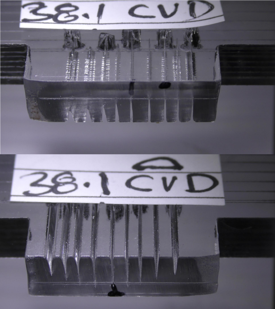
Something that is noticeable in many of these 38.1mm lenses is a short conical entrance , a waist at a constant depth followed by a ballooning of the cut.
Can anyone explain this phenomenon? It is very obvious here but it also observable in many of the 50.8mm lenses, but to a much lesser degree.


Note: On this test the ballooning starts at the surface.
The 2 Inch / 50.8mm Lenses


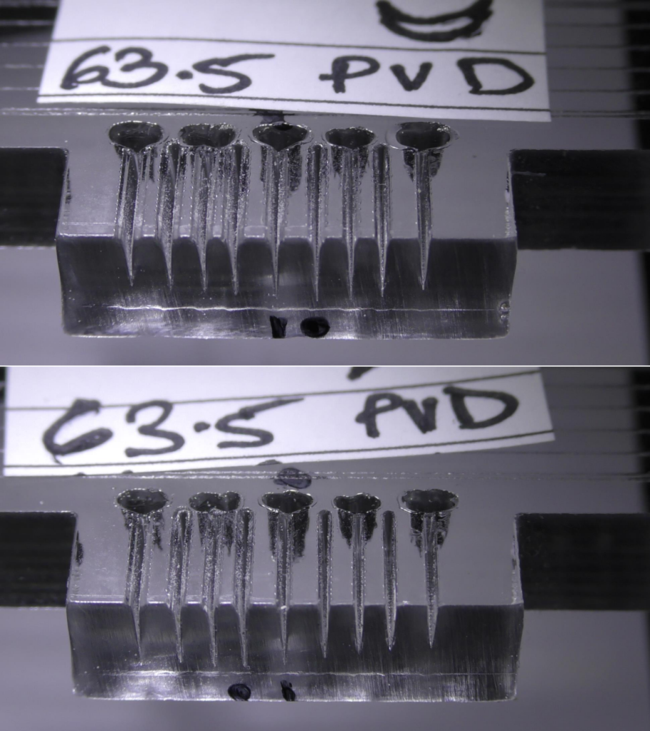
The 2.5″ / 63.5mm Lenses


The 4 Inch / 101.6mm Lenses


Beam Profiles at Differing Focal Depths
The following pictures illustrate the beam profile set at different focal depths. The “I” under a cut indicates the manufacturers focal distance which has been set onto the surface of the test piece. As you move to the left of “I”, the manufacturers focal point is being set 1mm deeper at each cut.
Moving to the right and the focal point is above the test piece surface and increases by 1mm for each cut.
The DOT indicates what I assess as the deepest cut. I.e. the red numbers in the table.
I also make an assessment of the thinnest surface line because this is the conventional means by which focus is set. I.e. the green numbers in the table.
You will note that there is ZERO predictability for any of these relationships and rarely do they coincide with the manufacturer’s focal point.
The 1.5″ / 38.1mm Lenses


The 2.0″ / 50.8mm Lenses


The 2.5″ / 63.51mm Lenses


The 4.0″ / 101.6mm Lenses