Session 06 – The Ruida Controller In Brief

The Concise RDWorks Learning Lab Series

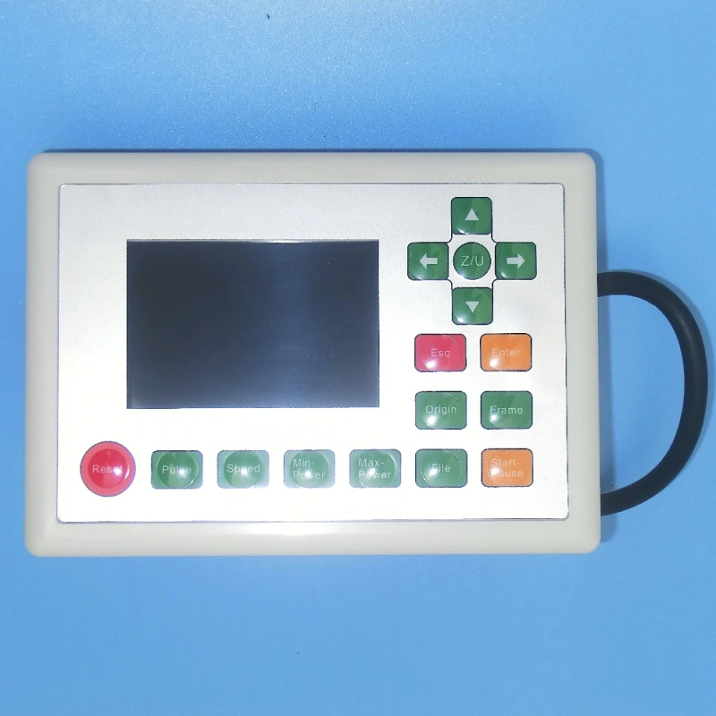
Welcome to the new Concise RDWorks Learning Lab Series with Russ Sadler. In this session, Russ briefly discusses the workings of the Ruida controller and goes through the key aspects of a typical laser machine circuit diagram. There are a number of Ruida controllers but the 6442S and 6442G are two of the more common variants.

Over the last 6 years, Russ has built up a formidable YouTube following for his RDWorks Learning Lab series which currently has over 200 videos.

The original RDWorks Learning Lab series on his “Sarbar Multimedia” YouTube Channel, follows Russ as he tries to make sense of his new Chinese laser machine and to sort out the truths, half truths and outright misleading information that is available on the web.

Six years later with over 4 million YouTube Views under his belt, Russ has become the go to resource for everything related to the Chinese CO2 laser machine user or wannabe user.

Ruida controller 644xg
Ruida Controller 644XG

In this new series, Russ has condensed his knowledge and experience of the last 6 years to provide valuable information and insights into the purchasing, understanding, use, repair and maintenance of the Chinese CO2 laser machines and their key component parts.

Previous VideoNext VideoSeries Menu

Podcast Download for the Ruida Controller in Brief

You can download the audio file for this video here, just click on the three dots to the right of the player:

Podcast Session 06 – The Controller In Brief
Image of ruida laser machine control panel
Ruida laser machine control Panel

Video Resource Files

Ruida Controller Manual

Possible Ruida Controller Passwords: RD8888 / rd8888 / HF8888 / hf8888 / CC8888 / cc8888. Make sure you have backups of your controller settings before using any of the above Ruida Controller passwords on your controller.

There are no more resource files associated with this video.

Ruida controller rdc644xg wiring schematic
Ruida Controller RDC644XG Wiring Schematic

External Resource Links

There are no external resource links associated with this video.

Reset Ruida Controller

If you need to reset your Ruida Controller to it’s DEFAULT Parameters as defined by your Laser System Manufacturer. This is the procedure to follow:

  • Back up your current files if not already done – This is a vital stage as not all Laser System Manufacturers will have loaded a default parameter file onto the controller and you may inadvertently revert to Factory Default. You can save the settings via RSWorks and LightBurn when your laser machine is connected to the software.
    • Backup with RDWorks: Open RDWorks > File > Vendor Settings > Password: RD8888 > Read > Save > Filename.RDVSet.
    • Backup with LightBurn: Open LightBurn > Edit > Machine Settings > Read > Save > Filename.lbset
  • With the Laser machine switched on press Z/U
    • Press Down Arrow to “Set Default Para” press <Enter>
    • Use keypad to enter the Password: HF8888
    • The controller will then beep and the message “Recover Success” will show.
    • Press <Enter>
    • Then reboot the controller by cycling the main power. Voilà, you now have a Reset Ruida controller!

Please Note: DO NOT carry out a Factory Parameters Reset!

Transcript for the Ruida Controller In Brief

Click the “Show More” button to reveal the transcript, and use your browsers Find function to search for specific sections of interest.

1
00:00:06,440 –> 00:00:14,930
The Concise RDWorks Learning Lab with Russ Sadler. Session 6: The Controller in Brief.

2
00:00:14,930 –> 00:00:24,270
OK, now we’re going to make a start on the controller. Now, what you see in front of you is basically the circuit diagram for the whole machine.

3
00:00:24,270 –> 00:00:29,310
But this big white block down the bottom right hand corner is the brains of the machine.

4
00:00:29,310 –> 00:00:38,070
Now, I’m going to call it a black box, even though it’s white, because what goes on inside there does not really concern us.

5
00:00:38,070 –> 00:00:44,720
There is a microprocessor in there and some fairly powerful programing, but,

6
00:00:44,720 –> 00:00:48,980
all we’re interested in is what goes in and what comes out.

7
00:00:48,980 –> 00:00:54,380
So let’s take a quick look around it and try and make some sense of it.

8
00:00:54,380 –> 00:01:00,650
Now, this top row of terminals is all to do with the outputs from the controller.

9
00:01:00,650 –> 00:01:05,090
The outputs that are actually controlling the machine and its motions.

10
00:01:05,090 –> 00:01:16,670
If we take a look at where these wires go to, you’ll see that some of these go to the motor driver X and the motor X, the driver Y and the motor Y.

11
00:01:16,670 –> 00:01:23,180
Well, let’s take a look along here and we shall see that we’ve got an x axis driver, a Y axis driver,

12
00:01:23,180 –> 00:01:29,150
a Z axis driver, which you probably won’t have because that’s for pushing the table up and down.

13
00:01:29,150 –> 00:01:35,840
You’ll only have this Z axis if you’ve got an auto focusing system built into your machine.

14
00:01:35,840 –> 00:01:47,960
Now, the next axis is called U, and basically it’s an uncommitted control system which allows you to drive a stepper motor,

15
00:01:47,960 –> 00:01:55,940
to activate a conveyor, to run your rotary system to do anything extra that you want

16
00:01:55,940 –> 00:01:59,390
with the machine. It’s just a spare output.

Transcript for the Ruida Controller In Brief (Cont…)

17
00:01:59,390 –> 00:02:07,430
Now, the next two are exactly the same as each other. CN5 is the one that you’ll find used on your machine.

18
00:02:07,430 –> 00:02:13,340
And only if you have a second later tube in your machine will you be using CN6.

19
00:02:13,340 –> 00:02:20,330
But CN5 is probably the most important connection set that you’ve got on your machine.

20
00:02:20,330 –> 00:02:26,340
And we’ll come onto that in a minute. Now, this other set of terminals along the bottom here,

21
00:02:26,340 –> 00:02:38,720
CN1 to CN4 are all to do with sensors and switches for telling the controller what’s going on around the machine.

22
00:02:38,720 –> 00:02:42,680
Now, I’m not going to get too involved with those at this point in time.

23
00:02:42,680 –> 00:02:46,010
Some of those will come into play later on when we talk about other things.

24
00:02:46,010 –> 00:02:52,880
Now, this row of LED’s across the top here have got numbers beside each LED, but they haven’t got any legend.

25
00:02:52,880 –> 00:03:01,610
Well, that’s because you can easily miss what these LEDs are, because right down the center of the box,

26
00:03:01,610 –> 00:03:07,970
there are a set of legends here which are numbered one to 15, which tells you exactly what these LEDs do.

27
00:03:07,970 –> 00:03:14,690
Now, when you first turn your machine on, the X and Y axis will run to one corner of the machine.

28
00:03:14,690 –> 00:03:24,180
It could be the left back. It could be the right back. But whatever happens if you take a look down here at CN4.

29
00:03:24,180 –> 00:03:29,820
You’ll find that there are some limit Switches on here and what will actually happen is those limit switches

30
00:03:29,820 –> 00:03:38,730
will be made, so that the machine knows where it’s zero zero point is for programing.

31
00:03:38,730 –> 00:03:44,040
And what will happen is, if you watch these LED’s, one, two, three and four,

32
00:03:44,040 –> 00:03:49,590
two of those will illuminate for a short period of time and then go out.

33
00:03:49,590 –> 00:03:55,290
And when they’ve both gone out, you’ll find that LED 14 flashes.

34
00:03:55,290 –> 00:04:00,090
That basically means that the machine is set and is ready to run.

Transcript for the Ruida Controller In Brief (Cont…)

35
00:04:00,090 –> 00:04:05,730
Now, I say that because several people have asked me and worried about the flashing LED 14.

36
00:04:05,730 –> 00:04:11,730
If we take a look at the top left hand corner there, we should see that the main’s comes into a filter.

37
00:04:11,730 –> 00:04:17,520
Now, that mains goes to three places around the machine, which are all red boxed for you.

38
00:04:17,520 –> 00:04:25,740
One of them is the 24 volt power supply. If you follow the wires through, that’s the power that goes and runs the controller.

39
00:04:25,740 –> 00:04:31,830
Now, the other place that the mains goes to is the laser power, high voltage power supply itself,

40
00:04:31,830 –> 00:04:37,980
because we need the alternating supply inside the power supply to generate incredibly high voltages.

41
00:04:37,980 –> 00:04:43,650
Basically, just like you do on your spark plug for your car, in a slightly more sophisticated manner.

42
00:04:43,650 –> 00:04:47,670
But that’s why we need the AC voltage into the power supply.

43
00:04:47,670 –> 00:04:54,930
Now, the other place that we’ve got the mains going to is into this DC 36 volts power supply,

44
00:04:54,930 –> 00:04:59,130
which basically supplies DC power to drive the stepper motors.

45
00:04:59,130 –> 00:05:08,660
So as you can see already with just a few simple descriptions, we’ve covered most of this circuit diagram. Now just down here,

46
00:05:08,660 –> 00:05:15,590
we’ve got the keyboard, which allows us to put a manual input into the brain,

47
00:05:15,590 –> 00:05:23,360
and over here we have a laptop or a computer which will connect somehow to the machine.

48
00:05:23,360 –> 00:05:30,590
Now, there are three ways that you can connect to the machine and get your programs from the computer into the brain.

49
00:05:30,590 –> 00:05:42,160
One of them is via a local area network an Ethernet system. One of them is via a direct link between the computer and the USB input.

50
00:05:42,160 –> 00:05:51,370
Now there is a third way and basically that is to use the PC to load the program onto a memory stick and you then plug that memory

51
00:05:51,370 –> 00:05:56,020
stick into the brain and offload the program that way.

52
00:05:56,020 –> 00:06:00,760
So there are three separate ways that you can get a program into the controller.

Transcript for the Ruida Controller In Brief (Cont…)

53
00:06:00,760 –> 00:06:12,070
Now, as I mentioned a few minutes ago, there are two vital connections out of CN5 that connect up to the Laser power supply.

54
00:06:12,070 –> 00:06:18,670
Now we’ve got the blue line here, that controls the later tube switching on and off.

55
00:06:18,670 –> 00:06:25,540
Now, if we look at the red line, you’ll see that it comes from a terminal which is marked up PWM.

56
00:06:25,540 –> 00:06:26,770
Now, we’re not going to explain that.

57
00:06:26,770 –> 00:06:35,860
We’re not really going to bother with it too much, except to say that it is an alternating signal which is generated by the controller,

58
00:06:35,860 –> 00:06:44,380
which varies according to the signal voltage that it wants to send out to the laser power supply.

59
00:06:44,380 –> 00:06:54,010
Now, the laser power supply has got an in-terminal and at that in-terminal, there is a little network which decodes that signal.

60
00:06:54,010 –> 00:07:04,060
Now, you’ll notice that beside that in-terminal, we’ve already got a five volt, but that’s a five volt output, not a five volt input.

61
00:07:04,060 –> 00:07:14,080
Now, on some of these controllers, if we look at Terminal one, on CN5 in this particular instance, it’s shown as a ground line.

62
00:07:14,080 –> 00:07:18,200
But on some controllers, that is actually an analog output.

63
00:07:18,200 –> 00:07:23,890
They do not use an encoded PWM signal for sending that information to the power supply.

64
00:07:23,890 –> 00:07:32,470
They use a direct analog naught to five volt signal to send it to the power supply via the same in-terminal.

65
00:07:32,470 –> 00:07:39,280
So there are two ways you can get a power demand signal into the laser power supply.

66
00:07:39,280 –> 00:07:45,800
Now, that power supply demand signal, which is naught to five volts.

67
00:07:45,800 –> 00:07:48,410
If you remember when we talked about the power supply,

68
00:07:48,410 –> 00:07:56,570
the power supply can deliver a maximum number of milliamps depending on the tube that it’s trying to control.

69
00:07:56,570 –> 00:08:00,410
We’re not actually controlling the power watts of the laser.

Transcript for the Ruida Controller In Brief (Cont…)

70
00:08:00,410 –> 00:08:04,370
What we’re doing that we’re controlling the current that flows through the tube.

71
00:08:04,370 –> 00:08:09,830
Now, these are the only two signal lines between the controller and the laser tube.

72
00:08:09,830 –> 00:08:14,390
And there are all sorts of wonderful tricks that you can play with these two lines,

73
00:08:14,390 –> 00:08:26,325
but we’ll come on to those tricks later on when we talk about various features of the machine.

Disclaimer

Last updated August 26, 2021

WEBSITE DISCLAIMER

The information provided by n-Deavor Limited, trading as Laseruser.com (“we,” “us” , or “our”) on (the “Site”) is for general informational purposes only. All information on the Site is provided in good faith, however we make no representation or warranty of any kind, express or implied, regarding the accuracy, adequacy, validity, reliability, availability or completeness of any information on the Site.

UNDER NO CIRCUMSTANCE SHALL WE HAVE ANY LIABILITY TO YOU FOR ANY LOSS OR DAMAGE OF ANY KIND INCURRED AS A RESULT OF THE USE OF THE SITE OR RELIANCE ON ANY INFORMATION PROVIDED ON
THE SITE. YOUR USE OF THE SITE AND YOUR RELIANCE ON ANY INFORMATION ON THE SITE IS SOLELY AT YOUR OWN RISK.

EXTERNAL LINKS DISCLAIMER

The Site may contain (or you may be sent through the Site) links to other websites or content belonging to or originating from third parties or links to websites and features in banners or other advertising. Such external links are not investigated, monitored, or checked for accuracy, adequacy, validity, reliability, availability or completeness by us.

WE DO NOT WARRANT, ENDORSE, GUARANTEE, OR ASSUME RESPONSIBILITY FOR THE ACCURACY OR RELIABILITY OF ANY INFORMATION OFFERED BY THIRD-PARTY WEBSITES LINKED THROUGH THE SITE OR ANY WEBSITE OR FEATURE LINKED IN ANY BANNER OR OTHER ADVERTISING.
WE WILL NOT BE A PARTY TO OR IN ANY WAY BE RESPONSIBLE FOR MONITORING ANY TRANSACTION BETWEEN YOU AND THIRD-PARTY PROVIDERS OF PRODUCTS OR SERVICES.

AFFILIATES DISCLAIMER

The Site may contain links to affiliate websites, and we receive an affiliate commission for any purchases made by you on the affiliate website using such links. Our affiliates include the following:

  • makeCNC who provide Downloadable Patterns, Software, Hardware and other content for Laser Cutters, CNC Routers, Plasma, WaterJets, CNC Milling Machines, and other Robotic Tools. They also provide Pattern Files in PDF format for Scroll Saw Users. They are known for their Friendly and Efficient Customer Service and have a comprehensive back catalogue as well as continually providing New Patterns and Content.
  • Cloudray Laser: a world-leading laser parts and solutions provider, has established a whole series of laser product lines, range from CO2 engraving & cutting machine parts, fiber cutting machine parts and laser marking machine parts.
Item added to cart.
0 items - £0.00