 Skip to content
 The Concise RDWorks Learning Lab Series
In Session 12, Russ switches the machine on and explains what happens during the Ruida controller start-up and homing sequence.
This session covers machine homing, X/Y proximity sensors, soft travel limits, the RDC6442 status LEDs and diagnostic screen, what happens when a stepper axis loses position, cable-chain faults and the different ways water-protection systems can be integrated into a CO₂ laser.
What You Will Learn in This Session
The controller cannot reliably use its configured work area until it knows where the machine datum is. On a typical Ruida-controlled flatbed CO₂ laser, that reference is established during start-up by moving the X and Y axes towards their home sensors.
What Happens When the Machine Starts
When the machine is powered up or reset, the controller runs a homing routine. The exact sequence depends on the machine configuration, but the purpose is to establish a repeatable X/Y machine origin before normal positioning begins.
Once home has been established, the controller can apply the configured travel range as a software limit. For example, if the machine is configured as 500 mm in X and 300 mm in Y, the controller normally restricts commanded movement to that working envelope measured from the established home position.
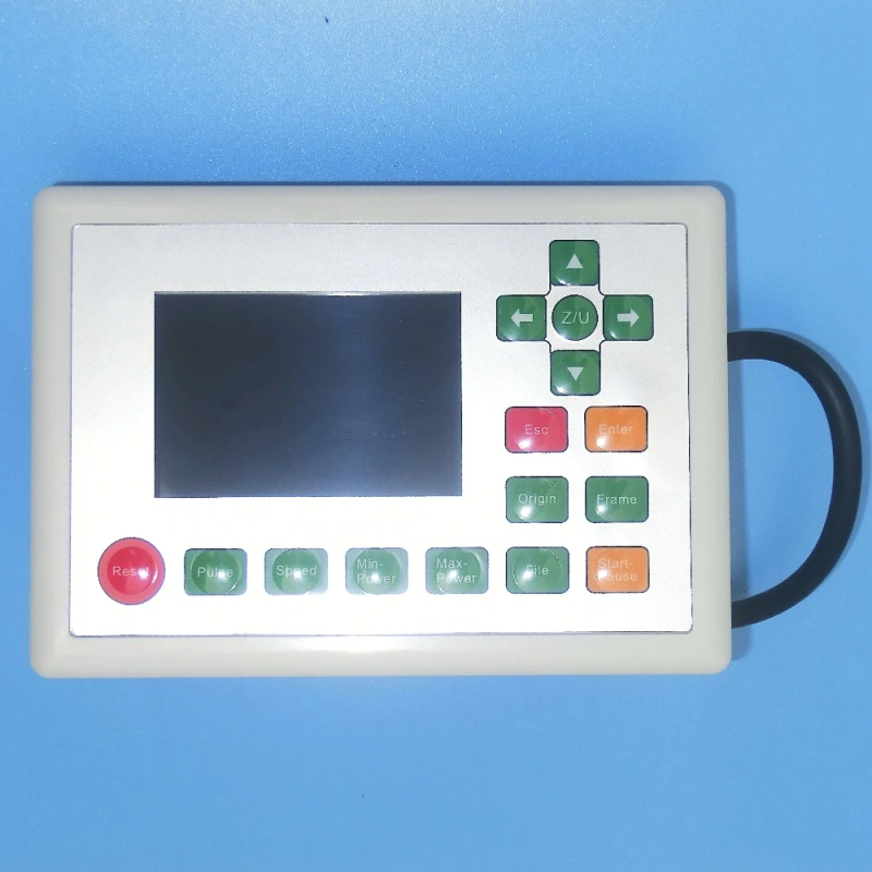
X and Y Home Sensors
The metal-detecting devices Russ demonstrates are best described here as proximity/home sensors. On the type of machines being discussed, these X and Y sensors are normally used to establish the home position rather than as physical end-of-travel switches at both ends of each axis.
Once the datum has been established, normal X/Y travel is generally controlled by the machine dimensions stored in the Ruida parameters. Although Ruida controllers such as the RDC6442, RDC6445 and RDC8445 can support hard-limit or hard-spacing functions, machine builders do not necessarily wire or use them in the same way.
The Z axis is often different. Many machines use simple mechanical spring-arm limit switches on the powered table. Moving the arm operates the switch and changes the circuit state so that the Z system can stop before mechanical over-travel.
Why the Homing Movement Repeats
Russ shows the carriage approaching a home sensor, moving away and then approaching it again more slowly. That second approach improves repeatability because the final datum is established from a slower, controlled sensor transition rather than from the first faster contact with the sensing zone.
The exact speeds, direction and sequence are machine parameters, so another Ruida-controlled laser may not look identical during start-up.
The Controller Usually Knows Commanded Position, Not Actual Position
Most machines of this type use open-loop stepper motion. The controller issues step commands and calculates position from those commands; it does not normally receive feedback confirming that every commanded step was physically completed.
This matters if the nozzle catches a raised workpiece, the carriage is obstructed or an axis reaches a hard stop. The motor can lose steps while the controller continues updating its internal coordinate. The displayed position can then differ from the real position of the head.
Why Russ Demonstrates the Hard-Stop Noise
The grinding or buzzing sound demonstrated in the video can be startling the first time a user hears it. It is typically the stepper motor being commanded to continue moving when the mechanism cannot move any farther.
The demonstration is useful because it shows what a lost-position condition sounds like and why the controller’s coordinate can become wrong. It should not, however, be treated as a routine method for establishing position by deliberately holding an axis against a hard stop.
Reset Is Useful After Lost Steps
If an axis has lost steps — for example because the nozzle caught the material — pressing Reset can re-run the homing sequence and restore the controller’s relationship with the real machine position.
If the same fault repeats, do not keep resetting and carrying on. Investigate the cause: material height, nozzle clearance, obstruction, belt or bearing problems, homing sensor operation, wiring or another mechanical fault.
RDC6442 LEDs Are Useful Diagnostic Indicators
Russ then moves to the RDC6442 controller itself and shows its status LEDs. These can be extremely useful because they allow you to see whether particular inputs are reaching the controller during start-up and fault-finding.
The LED numbering and meanings shown in this session are RDC6442-specific. Do not assume that an RDC6445, RDC8445 or another Ruida controller has the same physical LED arrangement or that a particular LED number has the same meaning.

A Sensor LED Does Not Prove the Controller Is Receiving the Signal
A particularly useful troubleshooting point in the video is the distinction between the indicator on the sensor and the state seen at the controller.
A proximity sensor can illuminate locally while the controller fails to see the input. The fault may be in a connector, termination, conductor or cable chain. Some machines use sensors with captive leads rather than plug-in terminals, so an intermittent fault can require cable repair or replacement depending on where it is found.
The controller’s diagnostic display or board input indication is therefore a better end-to-end check than relying only on the sensor’s own LED.
Cable-Chain Faults Can Be Intermittent
Repeated flexing in a cable chain can eventually damage conductors, particularly where the cable selection, bend radius or routing is poor. A broken conductor may make and break contact as the gantry moves, producing an intermittent homing fault that is difficult to reproduce while the machine is stationary.
Russ’s suggestion to consider the complete moving cable path is therefore sound, but replacement of the sensor and the entire cable is not automatically required. Diagnose whether the problem is the sensor, termination, connector, cable or controller input before deciding on the repair.
The Controller Diagnostic Screen Helps Confirm Inputs
The RDC6442 diagnostic menu gives another way to confirm whether the controller is seeing the X and Y home inputs. This is particularly useful when the sensor itself appears to operate but the machine does not home correctly.
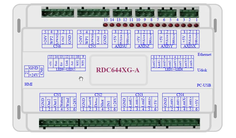
Water Protection Varies Between Machines
The audible water-flow warning Russ demonstrates is specific to the way that particular machine is wired. CO₂ laser builders use several different arrangements.
- The flow or chiller signal can be connected to the Ruida controller’s Water Protect (WP) input, allowing the controller/HMI to report the fault and inhibit laser operation.
- Some machines connect water protection directly to the high-voltage laser power supply so that the tube cannot fire when cooling protection is open.
- Some integrate the signal into a wider safety or door-interlock circuit.
- The signal itself may come from equipment such as a CW-3000, CW-5200 or a separate flow sensor, depending on the cooling system.
Where the controller supports it, using the Ruida WP function is generally the clearest arrangement because it allows the controller to know why laser firing has been inhibited and present a meaningful fault indication to the operator.
Different Machines Can Home to Different Corners
Russ demonstrates two machines whose datum positions are in different rear corners. That is normal: the home direction depends on the machine builder’s mechanical layout, sensor positions and controller parameters.
Machine home, machine coordinates, user origin and the job’s start position are related concepts but are not the same thing. Establishing machine home gives the controller its physical reference; later software settings determine how a particular job is positioned within that coordinate system.
Practical Start-Up Troubleshooting
- If an axis does not move towards home, check controller state, drive power and the relevant home input.
- If the sensor LED changes but the controller input does not, inspect the wiring path, terminations and cable chain.
- If the head reaches the home area but keeps driving, check that the controller actually sees the home input and that its polarity/configuration is correct.
- If the head position becomes wrong after a collision or obstruction, reset/re-home the machine to restore the coordinate reference.
- If the fault repeats after a reset, troubleshoot the underlying mechanical, sensor or wiring problem rather than repeatedly forcing the machine through the same failure.
Key takeaway: the homing sequence establishes the physical reference that makes the controller’s X/Y soft limits and coordinate system meaningful. Understanding the sensors, controller inputs and open-loop stepper behaviour makes start-up faults much easier to diagnose.
Podcast Download
You can download the audio file for this video here, just click on the three dots to the right of the player:
Video Resource Files
The Ruida RDC 6442 Control System Manual
Ruida Controller 6442 Wiring Instructions
The supporting controller illustrations previously shown in the resource sections have been retained above beside the relevant lesson sections.
External Resource Links
RDWorks V8.01.54 Software manufacturers site
Transcript for Let’s Switch The Laser Machine On
The original transcript remains part of the source lesson. It records Russ’s spoken explanation as presented in the video; the derived lesson notes above add clarification where machine configuration or current service practice requires more context.
Disclaimer
Last updated August 26, 2021
WEBSITE DISCLAIMER
The information provided by n-Deavor Limited, trading as Laseruser.com (“we,” “us” , or “our”) on (the “Site”) is for general informational purposes only. All information on the Site is provided in good faith, however we make no representation or warranty of any kind, express or implied, regarding the accuracy, adequacy, validity, reliability, availability or completeness of any information on the Site.
UNDER NO CIRCUMSTANCE SHALL WE HAVE ANY LIABILITY TO YOU FOR ANY LOSS OR DAMAGE OF ANY KIND INCURRED AS A RESULT OF THE USE OF THE SITE OR RELIANCE ON ANY INFORMATION PROVIDED ON
THE SITE. YOUR USE OF THE SITE AND YOUR RELIANCE ON ANY INFORMATION ON THE SITE IS SOLELY AT YOUR OWN RISK.
EXTERNAL LINKS DISCLAIMER
The Site may contain (or you may be sent through the Site) links to other websites or content belonging to or originating from third parties or links to websites and features in banners or other advertising. Such external links are not investigated, monitored, or checked for accuracy, adequacy, validity, reliability, availability or completeness by us.
WE DO NOT WARRANT, ENDORSE, GUARANTEE, OR ASSUME RESPONSIBILITY FOR THE ACCURACY OR RELIABILITY OF ANY INFORMATION OFFERED BY THIRD-PARTY WEBSITES LINKED THROUGH THE SITE OR ANY WEBSITE OR FEATURE LINKED IN ANY BANNER OR OTHER ADVERTISING.
WE WILL NOT BE A PARTY TO OR IN ANY WAY BE RESPONSIBLE FOR MONITORING ANY TRANSACTION BETWEEN YOU AND THIRD-PARTY PROVIDERS OF PRODUCTS OR SERVICES.
AFFILIATES DISCLAIMER
The Site may contain links to affiliate websites, and we receive an affiliate commission for any purchases made by you on the affiliate website using such links. Our affiliates include the following:
- makeCNC who provide Downloadable Patterns, Software, Hardware and other content for Laser Cutters, CNC Routers, Plasma, WaterJets, CNC Milling Machines, and other Robotic Tools. They also provide Pattern Files in PDF format for Scroll Saw Users. They are known for their Friendly and Efficient Customer Service and have a comprehensive back catalogue as well as continually providing New Patterns and Content.
- Cloudray Laser: a world-leading laser parts and solutions provider, has established a whole series of laser product lines, range from CO2 engraving & cutting machine parts, fiber cutting machine parts and laser marking machine parts.
