 Skip to content
 The Lightblade Learning Lab with Russ Sadler
The Lightblade Learning Lab is a series of videos that Russ did for Thinklaser Limited based on using the Lightblade 4060 Laser Cutting and Engraving Machine. Thinklasers Lightblade 4060 has a 400 x 600mm bed size and was supplied with a 60W EFR laser tube. In this session, Russ will teach us how to laser engrave a picture.
Contents
- Russ has already documented his learning process on the following RDWorks Learning Lab videos:
- Scanning two images – a comparison between two different techniques
- Looking at the different ways they were produced in RDWorks
- Outline fonts (vectors) and bitmaps
- Running a simulation to how the laser would engrave them
- Pixels
- Resolution and PPI (pixels per inch)
- Converting between PPI and Pixels per Millimetre
- Increment in mm (0.0847)
- Dots per inch
- Bitmaps create dots on the laser, vectors create lines
- Increment with vectors determines distance between lines
- Example of a piece of Perspex with a bitmap image of dots
- Common focal lengths and their theoretical spot sizes
- Effect of power on dot size
- For fine resolution we need a short focal length lens and very low power
- Effect of speed – elongation of dot
- Narrowing effect of speed on a more powerful pulse
- Different shades of brown on paper with different powers
- Doing the calculations to get the parameters for good clean dots:
- it works out that a ‘golden’ number is 5 ms/pixel of the picture
- Effects of different materials
- Dot sizes in relation to different resolutions
- Looking at how fast the laser can pulse, a test piece in Perspex to show this.
- Profiles of individual pulses versus ones which are fired in quick succession.
- The effect of the time it takes the beam to switch on and off.
- The ‘pseudo greyscale’ effect.
My thanks go out to Tom at Thinklaser for giving permission to embed these videos on this site. If you are looking for a new laser machine from a quality supplier, then I would suggest you check out their website: www.thinklaser.com.
Video Resource Files
There are no more resource files associated with this video.
External Resource Links
There are no more external resource links associated with this video.
Transcript for How to Laser Engrave a Picture
Click the “Show More” button to reveal the transcript, and use your browsers Find function to search for specific sections of interest.
00:13
Welcome to another Lightblade Learning Lab, now today I’m going to attempt the
00:19
impossible
00:22
now you may laugh at this but I’m going to attempt to tell you virtually
00:27
everything that I know about graphics and how we deal with graphics on this
00:32
machine not I can hear you’re laughing because you think that I probably know
00:36
about that much about graphics because I’ve purposely steered away from the
00:41
subject up to now. We’ve talked a little bit about it and as you can see I can
00:47
make a moderate attempt at getting a picture down onto a piece of material
00:52
and I can show you quite a few more examples but that does not mean to say
00:57
that I actually know what I’m doing that was a bit like shooting bullets in the
01:02
dark yeah I fiddled around with a few parameters and I’ve got some reasonable
01:08
results which is promising for you guys because it means you don’t need to know
01:12
very much to get some sort of result but the problem there was I was having to
01:19
fiddle around to get the parameters so I decided I will embark upon trying to
01:26
understand what graphics was all about now I have documented all my mistakes
01:33
all my learning processes that I went through to get the information that I’m
01:38
going to pass on to you today if you want to go into great detail then you
01:42
should spend sorry you might want to waste a bit of time and look here at my
01:48
other video channel but to save you the tedium of doing that
01:53
I’m going to attempt the impossible today and put something like about six hours
01:58
worth of video into maybe three quarters of an hour
Transcript for How to Laser Engrave a Picture (Cont…)
02:03
so sit back be patient and we’ll see what we can do to explain this
02:09
subject to you in fairly simple terms in a way that you will fully understand what
02:15
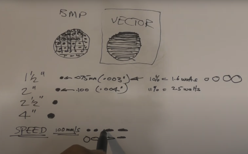
this machine can and cannot do in the way of graphics ok now I’m going to scan
02:21
two images on this page and I’m going to give you a clue they’re both going to be
02:28
scanned at the same speed and they’re both going to be scanned at the same
02:33
power, power is about 4 watts coming out of the tube minus the efficiency of all
02:40
the mirrors and the lens so there’s probably only about two and a half to
02:43
three watts arriving at the paper surface here so it’s a piece of white card
02:48
with two and a half watts going down onto the surface
02:54
now what I want you to do is the usual powers of observation to see if you can
03:00
determine the difference between scan one and scan two
03:47
well, what do you think do they look any different?
03:52
I think you’ll say the answer is no but believe me they are very different in
03:58
the way in which the machine has produced them that’s what the whole of
Transcript for How to Laser Engrave a Picture (Cont…)
04:02
this session is going to be about the difference between those two pieces of
04:07
text that actually look the same but they’ve got completely different
04:11
characteristics let’s go and have a look at what the
04:15
program is that I used to send those two pieces of information down to the Laser
04:20
machine. OK well here we are in RDWorks and you can see the two words text
04:28
on the screen now if we look up here at the top right hand corner you’ll see
04:34
that one of them is called BMP and the other is called nothing and that’s
04:42
because that second piece of text has been produced like this 50 millimeters
04:47
tall and I will change the font so that it doesn’t get confused with anything else
04:52
and we’ll turn it into a script font of some sort there we go like that not very
04:59
pretty but it demonstrates the point that I’m making when you create a piece
05:05
of text in RDWorks it comes in as an outline font now that outline is
05:13
basically a vector graphic outline and let’s just make it blue for a minute to
05:20
demonstrate put it onto a blue layer now that blue layer can either be set as a
05:29
scan layer which it is here or I can set it as a cut layer like that it doesn’t
05:39
look any different the only difference is the machine will treat it differently
05:43
this cut layer is exactly what it says if you cut that word text it will fall
05:48
out and leave a hole in your material if we
05:51
convert it to a scan layer as I said it looks no different at all but this time
05:57
something different will happen now you can see the other two pieces down here
Transcript for How to Laser Engrave a Picture (Cont…)
06:01
and there’s the big one at the top let’s just do a simulation and you will see
06:05
what happens now it’s going to scan from the bottom and when it gets to this one
06:13
it’s going to scan it lines across the page so the hollow text there basically
06:20
means it’s uncommitted you can have it cut or you can have it scanned now what
06:26
about the black text underneath well it’s come in as a bitmap you can’t
06:32
change that because that’s all to do with how you produce the text outside
06:37
this program and this piece of text has been produced in something like
06:43
Photoshop or some other art package where you might produce your drawings
06:49
and you import them into here as a bitmap or as a JPEG or a PNG or some
06:56
other form of basically a bitmap type file in reality when I engrave these
07:02
they both look the same but here as a text file as you can see it’s pretty
07:11
blocky around the edge now I might be talking
07:15
down to a lot of you guys but there’ll probably be people out there that do not
07:19
understand what a bitmap is in relation to a vector file which is the text drawn
07:24
above it okay well here we are close in on our two pieces of test text and I
07:29
don’t think you can really see any raggedness around them around the edge of
07:34
the bottom set of text it’s still pretty clean that is solid black text now
07:42
although this is a very largely magnified part of a picture I think
07:46
you’ll be able to see that there is an eye in that picture with a pupil and
07:50
iris around the outside it is not a solid color it’s made up of lots of
07:56
little pieces now those little pieces are called pixels and every one of those
Transcript for How to Laser Engrave a Picture (Cont…)
08:02
pixels on that screen there is mapped with an x and y-coordinate
08:09
so that the computer knows whether one pixel on the screen has got to be turned
08:14
black or white so there’s a huge amount of data that the computer
08:19
has to process to store a picture like this
08:23
now let’s just go and take a look what I mean by pixels and this strange word
08:30
called resolution the resolution of a picture is described in terms of PPI and
08:37
I’m going to draw this one at 300 PPI pixels per inch now that’s the standard
08:46
industry format for resolution and this particular picture is 300 PPI
08:53
horizontally and it’s also 300 PPI vertically makes sense because they’re
09:06
squares now when it comes to working in RDWorks most of you guys will have
09:16
your machines set to work in millimeters if you’re one of the very few people in
09:22
the world which probably includes America that uses inches still you will
09:28
otherwise have to use millimeters what we need to do is to establish what the
09:34
size of one of these pixels is okay now I’ve scribbled on this piece of paper
09:39
here a very simple calculation that you can carry out that will enable you to
09:44
convert from pixels per inch down to a size of a pixel so the first stage is to
09:51
take 300 pixels per inch and divide it by 25.4 now there are 25 point four
09:57
millimetres in an inch so what we’re really trying to do is to calculate the
Transcript for How to Laser Engrave a Picture (Cont…)
10:02
number of pixels in a millimeter and the answer to that is eleven point eight one
10:10
millimeters in a pixel so that’s pp millimeter pixels per millimeter now if
10:17
we want to find out the size of a pixel if we know how many pixels there are in
10:21
a millimeter if we divide the millimeter by eleven point eight one pixels it
10:27
tells us that we’ve got 0.0847 millimeters
10:31
is the size of that pixel there so that pixel there is 0.847
10:42
millimeters square at some stage when you’re setting up your scan parameters
10:47
you will be asked the question what is the increment and that will be asked
11:01
for in millimeters that’s the answer to the question Oh
11:06
eight four seven because you want to step down one pixel at a time in the
11:12
y-direction Right now, the Machine cannot produce square shapes it doesn’t
11:20
work in pixels per inch although pixels per inch is the thing
11:25
that drives the machine what actually comes out of the nozzle are round dots
11:32
you’ve seen it for yourself when you do a pulse burn down onto a piece of paper
11:38
if you set the focus right you get the very very fine dot the machine works in
11:46
dots per inch and the resolution of the picture that you’re trying to produce is
11:53
in pixels per inch you would say yeah but the machine is going to
11:58
automatically convert squares into dots as it runs across the page well you’re
Transcript for How to Laser Engrave a Picture (Cont…)
12:04
absolutely right every one of these squares tells the machine to do
12:11
something if we look at these pictures they do match up it decides whether it’s
12:16
going to put down a black dot nothing a black dot nothing black dot black dot black dot
12:22
now you might assume that that’s pretty logical most people don’t
12:26
understand that the machine can and does work in dots when it’s using a bitmap as
12:33
a driver I’m using that word a little bit carefully as a driver because there
12:38
is another thing that can be used as a driver now I’m just going to draw two
12:43
that look approximately like circles and this circle here is made up with pixels
12:57
and this circle here is not made up with anything at all this is a vector because
13:10
it has only got a ring around the outside and this one is a BMP it’s a circle made
13:18
up of squares how the Machine sees a bitmap every time, every time it sees one
13:24
of these pixels it sends out a pulse or not pulse or not not when we’ve got a
13:34
black picture like this which is filled in it’s filled in with a series of black
13:41
dots and it’s the collection of black dots that make the image look solid now
13:48
that’s not the same when we’ve got the vector drawing the laser doesn’t go and
13:52
put dots on here what it does it decides it’s going to scan backwards and
13:57
forwards across this image like this and as it goes across it’ll draw a line with
Transcript for How to Laser Engrave a Picture (Cont…)
14:03
the laser so we get a line that goes across there like that
14:08
and then it comes back and we get another line and then we get another
14:12
line we do not get dots we actually get lines that go backwards and forwards
14:17
across the image like this now I’ve purposely drawn these as lines with big
14:23
gaps between them but what you do this is where you set your increment and you
14:29
can set your increment so that the lines join up and that then becomes a solid
14:35
black shape as well but as you can see the mechanism by which the bitmap is
14:40
produced and the vector shape is produced are completely different
14:44
principles and that is a very very important thing that people do not know
14:50
or understand it took me a long time to find out this difference this is a piece
14:55
of perspex looking from the back of the perspex at
14:59
an angle so that what we can see is a black rectangle that I had produced and
15:06
the black, the black rectangle is obviously made up of every single dot in
15:13
the bitmap and you can see those dots on here now when you look at it from the
15:19
front it looks like a solid black shape but when you look at it from the back
15:23
you can clearly see that that solid black shape has been made up by dots
15:28
that join together now that is a very very important principle that you need
15:32
to understand about producing graphics well we’re not really going to talk much
15:37
more about this one because this one is very simple just lines and spacing
15:44
increments this is the one that’s very very interesting to explore because if
15:50
you want to put a photograph down onto a sheet of any material you will have to
15:58
use a bitmap image to start with because that’s what photographs are the cleanest
Transcript for How to Laser Engrave a Picture (Cont…)
16:04
way of producing a picture like this is probably to do it in Coreldraw and it
16:08
may will then give you a DXF output so that you can produce a vector file which
16:14
you can then engrave across and this is a nice simple way of producing block
16:20
graphics logos text all the complications and difficulties come with
16:26
doing something which is a bitmap and this is what I spent a huge amount of
16:32
time, trying to understand this took me quite a long time to find out and I was
16:39
quite staggered to find every dot in the bitmap can produce a signal for the
16:45
laser beam to pulse this picture depends upon the size of the dot itself and the
16:53
resolution of the picture now there are many different focal lengths of lenses
17:00
that you can use in these machines the most common ones are one and a half inch,
17:05
two inch, two and a half inch and four inch now
17:13
every one of those lenses has something called a theoretical spot size now that
17:19
is the smallest size dot you can produce with that lens and a two inch lens has
17:28
got one which is a little bit bigger and a two and a half inch lens has got one
17:32
that’s even bigger still and the 4 inch lens has got one that’s even bigger this
17:38
is about 0.075 millimetres which in old money is point zero zero three, three
17:49
thousandths of an inch and this one is point one zero zero which in old money
17:55
is point zero zero four thousandths of an inch and so they go on and they get
Transcript for How to Laser Engrave a Picture (Cont…)
18:02
bigger and bigger as the lens gets bigger this is probably the lens that
18:07
most of you will have the Lightblade machine is fitted with one of these now
18:13
in terms of size you can see that it is very very little difference now I don’t
18:20
know whether you can see that but that’s two of my grey hairs there, that hasn’t
18:25
helped my bald patch has it? The size of that hair is roughly point zero zero
18:31
three, three thousandths of an inch or 0.075 millimetres so that just gives you
18:36
an idea of just how small the spot size can be and this at point zero zero four
18:44
you would not be able to see the difference between a 3 thou and a four thou
18:48
hair so don’t get too concerned if you’ve got a two inch lens in your
18:53
machine because it is not going to be a disaster when it comes to doing bitmap
19:00
graphics it makes a big difference to the area the energy density you
19:05
concentrate 60 watts into that size and then put 60 watts into that size the
19:11
energy density there is almost well it is twice as high as it is in this one so
19:16
in terms of cutting power this change makes a big difference
19:22
but in terms of Engraving power it makes no difference at all
19:28
okay now I’ve just drawn up a few little features on here having decided this was
19:35
roughly the thickness of a human hair and we don’t have to worry about it in
19:38
terms of resolution ability to produce a dot what we have got to worry about now
19:44
is power because we can produce these dots at very very low powers but as soon
19:50
as we start putting power into the dot the dot starts doing this gets bigger
19:56
and bigger and bigger now that’s not what we want if we want fine resolution
Transcript for How to Laser Engrave a Picture (Cont…)
20:03
pictures we need the smallest dots that we can possibly get ultimately what
20:07
we’re trying to achieve is a picture made up of dots different density areas
20:13
just as you see them in a newspaper photograph if you look at it very
20:18
closely you’ll see that is exactly that a series of dots and in fact we’ve
20:22
already seen that today here’s how the eye can be fooled much much further away
20:27
and you wouldn’t even see these dots you just see what looks like a photograph a
20:33
grayscale photograph and that’s one of the magic tricks that that happens
20:39
between the eye and the brain it has this ability to heal over all these
20:43
little imperfections and produce a lovely picture for you to look at so we
20:49
need the smallest dots we can get and to achieve that we really are looking for a
20:56
small focal length lens and very low power now how does speed affect it? Well up
21:04
to about a hundred millimeters a second the dots really don’t change too much
21:10
away from Circular but if you start going 150 200, 300 and 400 millimeters a
21:17
second then here’s what happens your dot turns into a sausage a short sausage and
21:25
then the faster you go the longer the dot becomes but this black set of
21:33
pictures that I’ve drawn here is not quite right because
21:35
there’s another phenomenon that occurs in parallel with that now if you use a
21:40
larger power to start with you get a bigger dot and if you start then
21:47
increasing the speed of that larger power here’s what happens you get a
21:52
sausage but the sausage is smaller than the dot and as you increase the speed
21:57
the sausage gets narrower and narrower and so you get back much more towards
Transcript for How to Laser Engrave a Picture (Cont…)
22:03
the original dot size here so consequently if we start looking at how
22:08
these lines sausages now sit on this picture here bear in mind we get a pulse
22:16
for every pixel these are dots but we’re still going to get a pulse here a pulse
22:25
here and a pulse here so that means we’re going to get a dot there a dot
22:30
there and a dot there the dots are going to start joining up and they’re no longer
22:35
going to be seen as dots like that what we see is that now that looks much more
22:47
like the vector scan but it isn’t because it’s still driven by dots and
23:01
those dots that drive this are producing some really weird effects now it would
23:09
be very very nice if we could produce dots and our picture look like this but
23:15
when we actually burn dots into a piece of paper what we get is something like
23:21
this now we’ve got brown dots slightly brown dots and lots of other different
23:31
grades of brown dots in the background but hey if I was producing a proper dot
23:36
graphic like this all these dots would look the same it would look like the
23:44
measles they would all be nice and black and at the same quality
23:48
the question is why are they all different shades of brown, different
23:54
power the shade of brown tells us the amount of power that’s gone into the dot
23:58
how much the paper has scorched when we’re doing dot graphics like this we
Transcript for How to Laser Engrave a Picture (Cont…)
24:03
have the power set to say eleven percent and eleven percent
24:10
Max and min there should be no variation in the grade of the dots they should all
24:16
be exactly the same little black dots but they’re not and the question is why
24:22
not now just coming back to this, this was done fifty millimeters a second very
24:31
slowly but it’s done with thirty percent power thirty-five or forty watts of
24:37
power coming out of the tube and this is a resolution of 100 pixels per inch
24:44
that’s what this picture was done at if we start going faster than that we lose
24:49
our individual dots and we get lines where the sausages are all joined
24:54
together so a hundred pixels per inch at 50 millimeters a second which enables us
25:00
to produce this lovely pattern here single dots is what I would class almost
25:06
as the Holy Grail that we’re looking for we’re looking for the ability to produce
25:10
good clean single dots to try and get my measles effect that I call it you know
25:16
we want nice uniform colored dots all over the picture so that we can produce
25:21
the same sort of picture that we produce with an inkjet printer just two colors
25:25
black and nothing so the background is left bare and every one of these little
25:31
burns is exactly the same color now that’s what we’re aiming for and this
25:36
looks as though it’s going to give us the parameters for achieving that so
25:41
here we’ve got 100 pixels per inch divide that by twenty five point four
25:45
means we’ve got three point nine four pixels per millimeter and so here we’ve
25:50
got fifty millimeters per second as the speed that we’re running it so if we
25:55
want to work out how long it takes for one millimetres worth of travel we take
Transcript for How to Laser Engrave a Picture (Cont…)
26:01
one millimeter we divide it by 50 milli we divide it by
26:05
50 and that basically gives us an answer of point zero two seconds per milliliter
26:12
20 milliseconds if we now take the 20 milliseconds in other words that’s how
26:18
much time it takes to travel a millimeter but we know that in a
26:22
millimeter we’ve got three point nine four pixels so if we take the time it
26:28
takes to travel one millimeter and divide it by the number of pixels in
26:33
that millimeter we get approximately let’s just call that four for example
26:38
four pixels per millimeter it’s nice simple calculation and we get
26:43
approximately five milliseconds per pixel so that’s the amount of time that
26:48
it takes to actually put one of these pulses down now if we start messing
26:57
around with anything faster than 5 milli seconds per pixel then which will start
27:03
producing something which is getting closer and closer to this so at the end
27:10
of the day the crucial thing is how much time we’re spending putting a pixel down
27:16
and that depends on the resolution of the picture and the speed at which we do
27:23
it if we want to remain at 5 milliseconds per pixel which really is
27:28
what I class is almost a golden number then we can either change the resolution
27:35
of the picture from say a hundred pixels per inch to 150 pixels per inch now that
27:40
we’re looking we can increase the resolution and make it a finer quality
27:43
picture but to do so what we’ve got to do is we’ve got to reduce the speed for
27:48
50 millimetres a second to 33 millimeters a second to allow the same
27:54
amount of milliseconds per pixel consequently we could also do it the
27:59
other way around we could make the picture much much coarser down to 50
Transcript for How to Laser Engrave a Picture (Cont…)
28:04
pixels per inch and then we could push the speed up to our hundred millimetres
28:09
a second which would still give us five milliseconds per pixel what I’m going to
28:14
do is to show you this information in a slightly
28:16
different way so Just remember we’ve got five milliseconds that we calculated
28:21
for 50 millimeters a second, a hundred PPI so for that resolution that’s how much time
28:28
we have for every pixel now what you see here is a relative set of resolutions
28:35
this is a hundred pixels per inch 150 300 and 600 PPI these are all drawn to
28:43
scale and what that means is the pixel size for 100 PPI 0.25 4 millimeters it
28:49
then drops to 0.169, 0.084 and 0.04, 0.04 is just over the thickness
28:57
of a human hair for every pixel so just to keep that in perspective now what
29:04
that means is as we’ve already seen at a hundred PPI we can calculate if we run
29:10
this at 50 millimeters a second and every one of these is run at 50
29:15
millimeters a second we’ve already calculated on the previous sheet that it
29:20
takes 5.08 milliseconds for a Travis across one pixel now if we start halving
29:29
or we go to 150 pixels per inch that changes to 3.39 milliseconds as
29:37
opposed to 5 and when we get to 300 pixels per inch it’s down at one point
29:43
six nine milliseconds and at 600 millimeters a second it’s down at 0.85
29:49
milliseconds so we’re getting incredibly short periods of time allowed for every
29:55
pixel now what I’m trying to illustrate with this drawing is that the time
Transcript for How to Laser Engrave a Picture (Cont…)
30:01
allowed for every pixel is getting less and less and less as you increase the
30:07
resolution you might think you’re doing a great job of increasing the definition
30:12
of your picture but what you’re actually doing is allowing less time for the
30:16
laser beam to burn in one spot and therefore the color of the spot will be
30:22
less dense now that’s true if you’re using
30:27
something like white card or an organic material like wood leather but of course
30:33
that won’t apply if you’re using glass or slate or granite or something like
30:39
that we get a completely different effect so let’s stay with white paper
30:43
card or wood where we get grades of brown depending on the power that we put
30:47
into the dot now things are starting to get quite complicated because although
30:52
I’ve broken this whole problem down into little individual elements like this
30:58
they don’t actually and can’t actually exist like this in reality typical dot
31:04
size for a two inch lens would be probably somewhere in the region of
31:08
about point two in practice I know theoretically it should be point one of
31:13
a millimeter but in practice when you start burning it you’ll find it very
31:17
difficult to get much less than point two of a millimeter so therefore when we
31:22
start looking at a point two millimeter pixel in here that’s what it looks like
31:29
now at 50 millimeters a second we’re talking about using small amounts of
31:36
power here by the way say eleven percent very very small amounts of power and we
31:41
get that sized pixel the best one that we can get now if we carry on using
31:45
eleven percent power and we move the resolution up to 150 PPI and we try and
31:51
put the same pixel on there that’s what we’re going to get we’re going to get a
Transcript for How to Laser Engrave a Picture (Cont…)
32:02
dot that overlaps with the next dot and then when we try and do it at 300 we’re
32:09
going to finish up with the same dot at the same dot but look what happens is
32:16
covering more and more pixels but remember the machine is driven by the
32:21
pixels so consequently what will happen is we shall get the first circle here to
32:28
match the first pixel and then the second pixel will drive another dot and
32:33
so we should get another dot here and then
32:36
third pixel will drive yet another dot and look I think you can see very
32:42
clearly that we’re getting dots overlapping on dots overlapping on dots
32:46
so we’re getting multiple multiple multiple burns and the finer the
32:51
resolution the more burns we get in X and of course then we start stepping
32:56
down in Y so we need to get multiple burns in X and in Y we’ve got a few
33:01
parameters that are getting mixed up here we’ve got the dot size which is
33:07
remaining constant even though the resolution is getting smaller and
33:12
smaller and finer so we’re getting more and more overlaps which technically
33:17
means we probably could be getting more darker burn but of course counteracting
33:23
the darker burn we’ve got the opposite effect and that is the fact we’re
33:27
getting less time for each one of these burns
33:30
so although we technically might have a darker burn because we’re getting
33:34
multiple burns we’re getting substantially less power
33:38
because there’s less time for the dot in one spot now you can’t second guess what
33:46
the result of this is going to be I’m just telling you what the problem is
33:50
that you’re facing what we should do is find out how these things affect a
33:56
picture in the next session when we start building pictures at different
Transcript for How to Laser Engrave a Picture (Cont…)
34:00
resolutions but for the time being what I’m trying to do is to explain to you
34:05
the problems that we’re going to face so that you can understand all the details
34:10
associated with producing graphics now you can see that we’ve got less and less
34:16
time here for our burn to take place but what we haven’t considered is whether
34:23
the machine itself can operate this fast for putting a pixel down and so I’ve
34:33
done some work on both of my machines to see how good they are at responding to a
34:40
demand for a pulse from each one of these pixels and we know that this one
34:46
works because there’s the picture and so I’ve done some more work at 50
34:52
millimeters a second and 100 PPI with a different pattern and I’ll show you the
34:58
results of that pattern what you’re seeing here is the penetration of the
35:04
beam into a piece of perspex now this is looking at it from the back so that we
35:12
can see the penetration into the perspex itself look you can see these little
35:16
Peaks so we’re looking at this from the backside at about 45 degrees so that we
35:22
can see the penetration and what I’ve done I’ve generated a pattern here which
35:28
is basically one pixel and this was all done at a hundred pixels per inch the
35:33
resolution so we’ve got one pixel and then we’ve got a four pixel gap two
35:38
pixels for pixel gap three pixels and a four pixel gap and we did that all the
35:42
way up to ten pixels and so that’s one two three four as it says on here I have
35:48
the tenth one is missing what we find is that the rise time the time that it took
35:55
for the beam to form that Green Line is virtually nothing this was nine pixels
Transcript for How to Laser Engrave a Picture (Cont…)
36:01
wide and what’s happened we’ve got some very strange effect taking place here
36:06
and then once the beam switch is off at about here we’ve got this pink line
36:10
which shows the decay of the beam the time that power actually takes to
36:16
disappear and so you can see that that pattern is exactly the same on every one
36:22
of these patterns here whether or not we’ve got one or nine pixel groups so
36:30
the rise and fall times are very consistent now the reason I’m showing
36:34
you this is because just one of these pixels that I’m showing you on here is
36:42
this so these are the single pixels that we can see here these pixels here in the
36:49
background are single pixels and they’re the same pixels as you see here now what
36:56
I’m now going to do is to just try and explain
37:01
what we see here with these funny shapes now on this pattern here I’ve just drawn
37:10
at just a nominal pixel pattern the black pixel nothing black pixel nothing
37:15
black black black nothing black black nothing black nothing black okay now what
37:21
we’ve got here is a little picture of the beam switching on and off and that’s
37:28
what that black pattern is in the background there that’s the maximum
37:32
power that we could expect the beam to achieve and this is theoretically what
37:38
we’re expecting to see we get a pulse here it is creating a black dot and then
37:45
we get no pulse so we get nothing then we get another black pulse and so it
37:50
runs and here where we’ve got a group of three we’ve got pulse pulse pulse we’ve
37:57
already proved that and I keep coming back to this picture so you don’t forget
38:01
it we’re driving this laser with individual pixel pulses and I’ll just
Transcript for How to Laser Engrave a Picture (Cont…)
38:08
remind you of this picture here Green is the beam on and pink is the beam
38:15
switching off and you can see how much drag or how much lag delay time there is
38:20
in switching the beam off the beam switches on and it never makes it to
38:26
this maximum that we were trying to go for the maximum power why not well
38:30
because it has to switch off and it takes a long time to switch off so
38:34
therefore it starts switching off early and it never makes it to this maximum
38:39
position and we can see that clearly on here look there is a one pixel there’s
38:46
two pixels and two pixels joined together are higher than one pixel three
38:52
pixels joined together are higher than two pixels four are higher than three
38:58
but then that’s where we start to stabilize out once we get to four pixels
39:02
we’ve achieved a uniform height so basically it takes almost four pixels to
39:08
reach the ideal depth the maximum depth now I haven’t quite shown that on this
39:12
diagram here but what we’ve got we’ve got
39:15
a rise time and a fall then we’ve got nothing a rise time and a fall
39:19
nothing then we’ve got a rise time and a fall but because we’ve got a pixel right
39:25
next to it it doesn’t get a chance to fall right the way back to zero so
39:29
consequently we rise again in the same time and we can climb the power a little
39:36
bit higher towards the target that we’re aiming for and then it falls and it
39:40
doesn’t drop down again as far and eventually after in this particular case
39:44
I’ve drawn it three pixels I’ve reached the maximum so and then we drop down
39:50
with two pixels we get to a different level with one pixel we get to this
39:55
level so basically what I’m saying is if we’ve got one pixel we achieve this much
Transcript for How to Laser Engrave a Picture (Cont…)
40:00
burn if we’ve got three pixels we can achieve this much burn and if we’ve got
40:07
two pixels we can achieve this much burn now that’s a variable amount of burn
40:14
depending on the grouping of the pixels it’s getting quite complicated the way
40:19
in which all these factors are interacting together but the point I’m
40:24
really making here is that this piece here is a constant so the amount of time
40:32
it takes for the beam to go up to a target value it’s aiming to get to 11%
40:37
remember but it never got to 11% because we didn’t give it enough time it had to
40:43
switch off this is why I keep laboring the point about these times and
40:47
milliseconds because 5 milliseconds here’s what the picture looks like now
40:55
there’s only 3 milliseconds we would have even less time to go up and come
41:00
down and goodness me look what happens at 0.85 milliseconds we get hardly a
41:06
chance to start before we’ve got to stop so what I’m really saying is here the
41:13
response time of the beam itself to turning its power on and turning its
41:20
power off to different levels can have quite a significant effect on the amount
41:25
of burn we get and the density of the burn that
41:30
we get on these pictures and remember earlier I was saying to you I was trying
41:37
to find an explanation why our dots were not all dark black well here we are
41:43
we’ve got different groups of dots here which operate at different powers where
41:50
we’ve got groups of three four and five dots up here we’ve got a dark burn but
41:55
where we’ve only got single dots we’ve got hardly any burn at all and
41:58
then we may have double dots and triple dots that isn’t what I was expecting but
Transcript for How to Laser Engrave a Picture (Cont…)
42:04
that’s what we’re going to get if we drive the resolution too high and if we
42:11
run the speed too high remember the resolution is going to
42:16
affect the time but of course this is at fifty millimeters a second so if I
42:23
increase that to 100 millimeters a second I would have half as much time on
42:28
each one of these and if I ran it at 200 millimeters a second I have a quarter
42:34
as much time so time is a most important factor because it’s all related to the
42:43
response capability of the power supply and the laser tube to produce a sharp
42:49
dot now that was hard work and I hope you’ve understood that it is the
42:55
explanation that I’m putting forward for this strange pattern of variable burns
43:00
you will see in the next session when I start doing some real pictures how this effect
43:07
this strange effect which I’m calling pseudo grayscale because technically
43:12
these should all be black all the same density but they’re not the same density
43:18
so we’ve got degrees of grayness in here but we’re not using grayscale this is
43:25
what I call a pseudo grayscale system well I’m going to leave you now where
43:30
we started this session off that there being a filled vector piece of text and
43:37
that being a bitmap piece of text now as I said to you they don’t look any
43:42
different but believe me I think after this session you can understand that
43:47
they are done in a completely different way now this is a very simple exercise
43:54
in the next session we shall deal with real photographs where I think you’ll be
44:00
quite surprised at some of the results we get
What Next?
Did you enjoy this post? Why not check out some of our other posts:
Disclaimer
Last updated April 25, 2024
WEBSITE DISCLAIMER
The information provided by n-Deavor Limited, trading as Laseruser.com (“we,” “us” , or “our”) on (the “Site”) is for general informational purposes only. All information on the Site is provided in good faith, however we make no representation or warranty of any kind, express or implied, regarding the accuracy, adequacy, validity, reliability, availability or completeness of any information on the Site.
UNDER NO CIRCUMSTANCE SHALL WE HAVE ANY LIABILITY TO YOU FOR ANY LOSS OR DAMAGE OF ANY KIND INCURRED AS A RESULT OF THE USE OF THE SITE OR RELIANCE ON ANY INFORMATION PROVIDED ON THE SITE. YOUR USE OF THE SITE AND YOUR RELIANCE ON ANY INFORMATION ON THE SITE IS SOLELY AT YOUR OWN RISK.
EXTERNAL LINKS DISCLAIMER
The Site may contain (or you may be sent through the Site) links to other websites or content belonging to or originating from third parties or links to websites and features in banners or other advertising. Such external links are not investigated, monitored, or checked for accuracy, adequacy, validity, reliability, availability or completeness by us.
WE DO NOT WARRANT, ENDORSE, GUARANTEE, OR ASSUME RESPONSIBILITY FOR THE ACCURACY OR RELIABILITY OF ANY INFORMATION OFFERED BY THIRD-PARTY WEBSITES LINKED THROUGH THE SITE OR ANY WEBSITE OR FEATURE LINKED IN ANY BANNER OR OTHER ADVERTISING.
WE WILL NOT BE A PARTY TO OR IN ANY WAY BE RESPONSIBLE FOR MONITORING ANY TRANSACTION BETWEEN YOU AND THIRD-PARTY PROVIDERS OF PRODUCTS OR SERVICES.
AFFILIATES DISCLAIMER
The Site may contain links to affiliate websites, and we receive an affiliate commission for any purchases made by you on the affiliate website using such links. Our affiliates include the following:
- makeCNC who provide Downloadable Patterns, Software, Hardware and other content for Laser Cutters, CNC Routers, Plasma, WaterJets, CNC Milling Machines, and other Robotic Tools. They also provide Pattern Files in PDF format for Scroll Saw Users. They are known for their Friendly and Efficient Customer Service and have a comprehensive back catalogue as well as continually providing New Patterns and Content.
- Cloudray Laser: a world-leading laser parts and solutions provider, has established a whole series of laser product lines, range from CO2 engraving & cutting machine parts, fiber cutting machine parts and laser marking machine parts.
