 Skip to content
 Foam can be one of the easiest materials to cut with a CO₂ laser — and one of the easiest to get badly wrong. The key differences compared with rigid sheet materials are material identification, heat control, air flow and the relatively large kerf that can develop in thick foam.
I originally investigated foam cutting because I wanted to replace the bubble-wrap packaging supplied with a Mahoney laser power meter. That project led to a useful set of real measurements for cutting 30mm polyethylene (PE) foam, including power, speed, dot-mode settings and kerf compensation.
Quick answer: how do you laser cut foam?
First, identify the exact foam rather than cutting an unknown plastic foam. For thick PE foam I get cleaner results by limiting heat input, using strong air assist and using a perforation/dot-style cut rather than simply applying high continuous power.
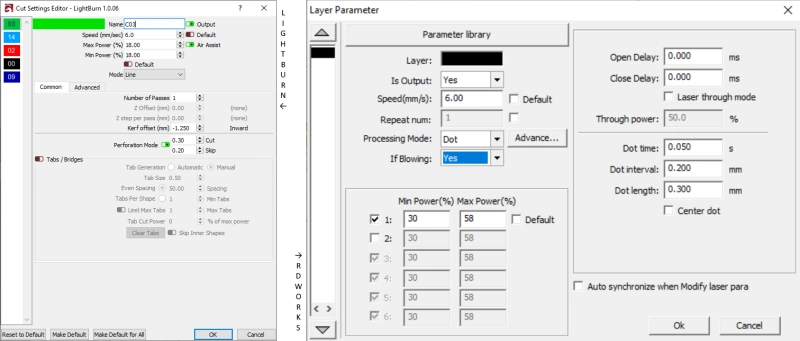
For the 30mm PE foam shown in this article, my starting point on my own CO₂ machine was:
- Power: 18% — approximately 20W on this particular machine
- Speed: 6mm/s
- LightBurn perforation: cut 0.3mm / skip 0.2mm
- RDWorks equivalent starting point: Dot Time 0.05s / Dot Interval 0.2mm / Dot Length 0.3mm
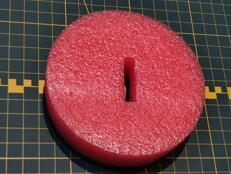
- Measured surface kerf: approximately 2.5mm
- Kerf compensation used: ±1.25mm, depending on whether I wanted an accurate hole or an accurate plug
These are machine- and material-specific starting points, not universal foam settings. Foam density, formulation, thickness, laser output, lens, focus and air assist can all change the result.
Which foams are suitable for laser cutting?
Polyethylene (PE), polyester (PES) and suitable polyurethane (PUR) foams are widely processed with CO₂ lasers. However, the polymer name alone is not enough to prove that a particular sheet is suitable. Commercial foams can contain pigments, fire retardants, adhesives, coatings and other additives.
Before cutting a new foam, identify the exact material and obtain the manufacturer’s technical or safety information where possible. If you cannot establish what the foam is made from, do not put it in the laser.
This is particularly important with insulation and specialist engineering foams. Products that look similar can be made from very different polymers. Never assume that colour, texture or a familiar brand name identifies the chemistry.
For broader material guidance, see What Can a Laser Cutter Cut? and the CO2 Laser Material Safety Database.
Foams to avoid or verify before laser cutting
I would not recommend expanded polystyrene (EPS) as a general-purpose foam for laser cutting. It melts readily and its fire behaviour makes it a poor choice where safer, better-behaved foam materials are available.
Foams containing PVC, fluoropolymers or other halogenated materials should not be treated like ordinary PE foam. Heating or laser processing some of these materials can produce corrosive and hazardous decomposition products. Unknown foam is therefore a do-not-cut material until its composition has been established.
Why dot or perforation mode works well on thick foam
Foam requires surprisingly little energy to remove material. The problem is often controlling where that energy goes. Too much continuous heat can enlarge the kerf, melt the cell structure and produce a heavily tapered cut.
Using dot/perforation mode interrupts the laser along the cutting path. On my 30mm PE foam this reduced continuous heat loading while still allowing the cut to progress through the material. In LightBurn I used a 0.3mm perforation cut followed by a 0.2mm skip. In RDWorks my equivalent starting point was Dot Time 0.05s, Dot Interval 0.2mm and Dot Length 0.3mm.
Step-by-step process for laser cutting foam
- Identify the material. Obtain a technical specification or safety information rather than guessing from appearance.
- Start with a test shape. I use a 25mm square because it lets me assess cut-through, taper and dimensional accuracy.
- Start conservatively. Use enough energy to cut through without unnecessarily melting back the foam. Denser or thicker foam will normally require more energy per unit length than a thinner or lower-density grade.
- Choose the lens for the thickness. A normal 2-inch lens can handle thinner foam. A 2.5-inch lens gives additional depth of focus, while a 4-inch lens becomes genuinely useful for specialist very thick, low-density foam such as the 30–40mm material discussed here.
- Support the foam and maintain airflow. I used a pin bed so air could move over and beneath the material.
- Use effective air assist. On my thick foam test I brought the nozzle to roughly 3mm above the surface. The optimum arrangement depends on the lens/nozzle geometry and foam thickness.
- Inspect both the hole and the plug. Thick foam can taper through its depth, so looking only at the top edge is not enough.
- Measure the kerf. Once the thermal settings are satisfactory, compensate for the actual cut width rather than changing the artwork by eye.
Which focal-length lens should you use for foam?
I no longer use a 4-inch lens as a general-purpose cutting lens. On a sub-80W CO₂ system it gives a larger focused spot and lower power density than shorter focal lengths, which can be counterproductive for materials such as acrylic.
Very thick foam is different. A 30mm or 40mm low-density foam does not demand the same power density, while the greater depth of focus of a long focal-length lens can be genuinely useful. This is one of the relatively few applications where I still see a good case for a 4-inch lens on a lower-power machine.
For ordinary thinner foam, use the normal lens already fitted to the machine and only move to a longer focal length when the material thickness or cut taper gives you a reason to do so.
Air assist and laser-bed setup
Air assist helps control local heating and moves smoke and decomposition products away from the cut. With very thick foam I found that bringing the nozzle close to the surface made the air assist more effective, although this also changes where the focal region sits through the thickness.
I prefer a pin bed for this type of work because it provides good airflow around the foam. If you have a honeycomb bed, raising the foam on suitable stand-offs can improve airflow and reduce contact with the bed. The same principle applies to lamellar/slat beds.
Whatever bed is used, extraction must be effective and the machine should remain supervised throughout the job. Foam can ignite, particularly if heat accumulates or a small feature causes the head to dwell in one area.
Managing the large kerf in thick foam
Kerf is the width of material removed by the cut. In rigid sheet materials it may be small enough to ignore for many jobs. Thick foam is different.
On my 30mm PE test material I measured a surface kerf of approximately 2.5mm. If the laser simply follows the centre of the artwork line, that dimensional loss matters.
There are two different requirements:
- Hole: the finished opening is the important dimension; the centre piece is waste.
- Plug: the cut-out centre piece is the required component.
For my 25mm test square, I arrived at a kerf offset of -1.25mm for accurately sized holes and +1.25mm for accurately sized plugs. The sign convention can depend on the software and geometry, so verify the result with a measured test rather than copying the number blindly.
Kerf compensation in RDWorks
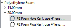
In RDWorks, the kerf controls are found in the Layer Parameter advanced settings and are labelled Sew Compensation / Sew Width. RDWorks normally follows the centre of the vector path, so compensation moves the effective cut path to correct the finished dimension.

Real project: protective foam for a laser power meter
The original reason for developing these settings was a Mahoney laser power meter. The meter is an irregular shape and needed to sit upright inside a cylindrical storage tube approximately 240mm tall and 104mm in diameter, with protection above and below the glass face.

I used seven layers of foam cut to the internal diameter of the container plus a separate foam disc attached to the lid. Different layers contained different openings so that, once stacked, they formed a shaped cavity around the meter.
- Layer 1 used a 32 × 8mm recess. I reduced the power so it did not cut completely through and removed the internal material.
- Layers 2–5 contained a 32 × 8mm through-slot.
- Layer 6 combined the slot with a 26mm diameter opening.
- Layer 7 contained an 80mm opening.
- The lid used an 80mm diameter foam plug.


Bonding the layers
For this prototype I simply used 24mm-wide double-sided tape to bond the layers together and attach the upper disc to the lid. If you use adhesive-backed foam or another adhesive system, check the adhesive as well as the foam itself before laser processing. Do not assume that a laser-compatible foam makes an unknown adhesive safe to cut.
Applications for laser-cut foam
Foam is useful wherever an object needs to be located, protected or made visually obvious when missing. Applications include tool drawers, flight cases, instrument packaging, camera equipment, samples, presentation cases and collection storage.
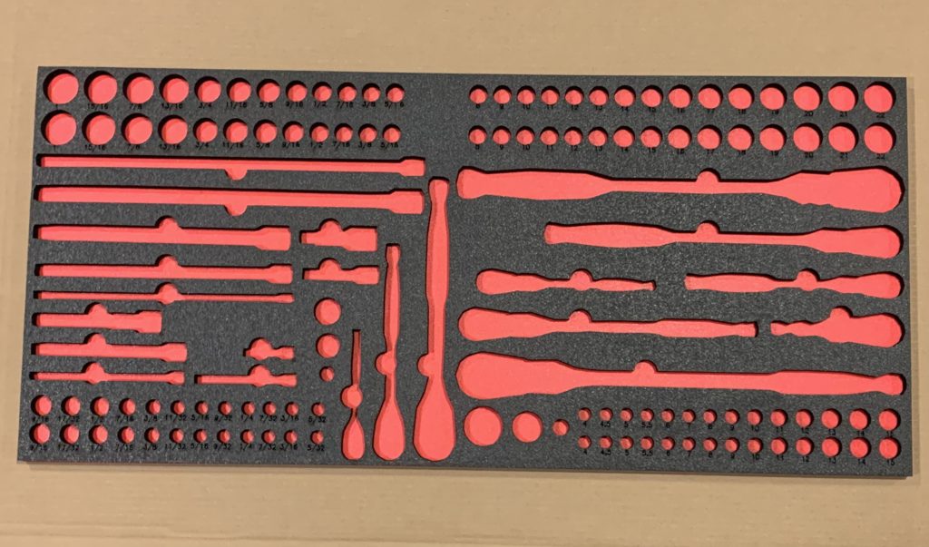
One client used a specially designed 1300 × 500mm foam drawer insert to store a collection of Welsh love spoons. The same principles of accurate cutting and kerf control apply whether the job is a small instrument case or a complete tool drawer.
For the complete workflow from photographing tools through to creating the finished drawer layout, see How to Laser Cut Foam Inserts for Tool Boxes.
Can you laser engrave foam?
Many known laser-compatible foams can also be engraved, but material identification still comes first. Do not assume that an unknown insulation foam is suitable simply because another foam of the same colour or texture engraved successfully.
On my 50W CO₂ machine, a typical experimental starting point has been around 20% power, 400mm/s and a 0.2mm scan interval. On that machine 20% corresponded to roughly 18W of measured optical output. Treat those figures as a starting point for testing, not a material preset.
Foam can melt back rapidly if too much energy is deposited in one area. For deeper engraving, do not simply slow the machine and assume the result will improve. Test power, speed and pass count systematically while watching the edge and cell structure. Multiple lighter passes may sometimes give better control, but reheating the same area can also accumulate heat, so inspect the result between passes.
Contrast is material-dependent. Some colours produce almost no visible change, while others develop a useful mark. A deeper recess can also appear darker because of shadow rather than an actual colour change.


Common foam-cutting problems
| Problem | Likely cause / what to test |
|---|---|
| Foam melts back around the cut | Too much local heat; test lower power, different speed or interrupted/dot cutting. |
| Very wide kerf | Excess heat, large spot or focus position; optimise the thermal settings before compensating the artwork. |
| Cut does not reach the bottom | Insufficient energy through the full thickness; check focus/depth of focus, power, speed and material density. |
| Strong taper | Beam geometry, heat spread and thickness; try a longer focal-length lens on genuinely thick foam and retest focus position. |
| Poor dimensional accuracy | Measure the actual kerf and use separate compensation for holes and plugs. |
| Heavy smoke or unexpected odour | Stop and verify the material. Odour is not a reliable safety test. |
| Flare-up or flame | Stop the job; review material suitability, airflow, extraction, power and speed before continuing. |
Frequently asked questions
Can a CO₂ laser cut polyethylene foam?
Yes, known suitable PE foam can cut very well with a CO₂ laser. My example in this guide is 30mm PE foam, but settings vary significantly with density, thickness and machine configuration.
What power should I use to laser cut foam?
There is no universal percentage. On my machine I used 18% — about 20W measured optical output — at 6mm/s for a particular 30mm PE foam. Use material testing to establish settings for your own machine and foam.
Is a 4-inch lens best for cutting foam?
Not for foam generally. A 4-inch lens becomes useful when cutting very thick, low-density foam because of its greater depth of focus. For thinner foam, a standard 2-inch or 2.5-inch lens may be entirely adequate.
Why is the kerf so large in thick foam?
The laser is not only removing material along an infinitesimally thin line; heat spreads into the foam and the cellular structure can melt back. My 30mm PE sample produced about a 2.5mm surface kerf, which is why dimensional compensation was important.
Conclusion
Good foam cutting is mainly about controlling heat and knowing exactly what material you are processing. With suitable PE foam, strong air assist, appropriate focus and measured kerf compensation, even 30mm material can produce clean and surprisingly accurate components on a relatively modest CO₂ laser.
The settings in this article are valuable because they are real measured results, but they should be used as a starting point for your own tests rather than copied as universal presets.
What Next?
Did you enjoy this post? Why not check out some of our other posts:
Disclaimer
Last updated April 25, 2024
WEBSITE DISCLAIMER
The information provided by n-Deavor Limited, trading as Laseruser.com (“we,” “us” , or “our”) on (the “Site”) is for general informational purposes only. All information on the Site is provided in good faith, however we make no representation or warranty of any kind, express or implied, regarding the accuracy, adequacy, validity, reliability, availability or completeness of any information on the Site.
UNDER NO CIRCUMSTANCE SHALL WE HAVE ANY LIABILITY TO YOU FOR ANY LOSS OR DAMAGE OF ANY KIND INCURRED AS A RESULT OF THE USE OF THE SITE OR RELIANCE ON ANY INFORMATION PROVIDED ON THE SITE. YOUR USE OF THE SITE AND YOUR RELIANCE ON ANY INFORMATION ON THE SITE IS SOLELY AT YOUR OWN RISK.
EXTERNAL LINKS DISCLAIMER
The Site may contain (or you may be sent through the Site) links to other websites or content belonging to or originating from third parties or links to websites and features in banners or other advertising. Such external links are not investigated, monitored, or checked for accuracy, adequacy, validity, reliability, availability or completeness by us.
WE DO NOT WARRANT, ENDORSE, GUARANTEE, OR ASSUME RESPONSIBILITY FOR THE ACCURACY OR RELIABILITY OF ANY INFORMATION OFFERED BY THIRD-PARTY WEBSITES LINKED THROUGH THE SITE OR ANY WEBSITE OR FEATURE LINKED IN ANY BANNER OR OTHER ADVERTISING.
WE WILL NOT BE A PARTY TO OR IN ANY WAY BE RESPONSIBLE FOR MONITORING ANY TRANSACTION BETWEEN YOU AND THIRD-PARTY PROVIDERS OF PRODUCTS OR SERVICES.
AFFILIATES DISCLAIMER
The Site may contain links to affiliate websites, and we receive an affiliate commission for any purchases made by you on the affiliate website using such links. Our affiliates include the following:
- makeCNC who provide Downloadable Patterns, Software, Hardware and other content for Laser Cutters, CNC Routers, Plasma, WaterJets, CNC Milling Machines, and other Robotic Tools. They also provide Pattern Files in PDF format for Scroll Saw Users. They are known for their Friendly and Efficient Customer Service and have a comprehensive back catalogue as well as continually providing New Patterns and Content.
- Cloudray Laser: a world-leading laser parts and solutions provider, has established a whole series of laser product lines, range from CO2 engraving & cutting machine parts, fiber cutting machine parts and laser marking machine parts.
