 Skip to content
 50 Watt CO2 Laser with 300 x 500mm Bed Size
Having recently been made redundant, I was finding it difficult to find a suitable alternative in my preferred laser sector. It was clearly time I went about buying a laser engraving and cutting machine to act as a possible second income stream.
So, how to go about buying a laser engraving and cutting machine?
Determine the maximum machine size you can fit in the available space. Work out your budget; include the cost for a replacement laser tube, laser PSU plus any import duties & taxes. Check out the forums and ask for recommendations. If you are new to lasers, make customer support a priority.
Obviously, there was a lot more to it than that, especially as it was my plan to take a cheap basic laser machine and upgrade it to something special!
How do you choose the best laser cutter for your needs?
With a limited budget, as well as planning to site the machine in my attic. I had to limit myself to a smaller machine as it had to go up two flights of stairs.
I started looking into some of the lower end suppliers of laser systems but didn’t find something that I considered to be both robust and good value. As I have some experience of laser machines already, I wanted to reduce costs by installing myself and this was not always an option with suppliers.
While I was drawing up a shortlist of machines, Russ Sadler (YouTube Channel Sarbar Multimedia) started a new laser series called “Tangerine Tiger” where he planned to install a RF Laser source into a basic Chinese laser cutting & engraving machine, together with a few of his choicest machine upgrades he has developed over the last 4 years, with a view to challenge the “big boys” of the CO2 Flatbed sector. I’ve worked with Russ previously (YouTube Channel Thinklaser), so I gave him a call to get the lowdown on the Tangerine Tiger machine he recently purchased.
Mechanically, the machine was basically sound, but Russ had already come across some worrying things relating to the electrical wiring (I’ll go further into this in another post). Luckily, I have an electronics background, so this didn’t worry me too much. In addition, the laser tube and laser PSU (Power Supply Unit) were most likely B Grade units, but I could cost in suitable replacements at a later date.
So What Did I Buy?
So I bit the bullet and placed my order on eBay with a Chinese / German (Cherman???) vendor for a laser cutting and engraving machine with the following specifications:
- 500 x 300mm (19.7 x 11.8″) bed size
- 50W rated laser tube which is most likely 40~45W as the tube was only 53mm in diameter and 800mm long. (check out my post “How To Get A Longer Life From Your Laser Tube” for more information on CO2 laser tubes)
- 50W laser PSU
- Red dot pointer
- Ruida RDC6442S controller
- RDWorks
- Pass through port (500 x 50mm)
- Motorised Z-axis, 210mm travel with up/down buttons
- Air assist pump
- Water pump
- Water flow sensor
- 230V / 0.3A extraction fan
- Various accessories and even some manuals
- CE marked (actually meaning “Chinese Export” not “Conformité Européenne” (French), which means European conformity.)
- Dimensions: 1020 (W) x 590 (H) x 670 (D)mm 40″ x 23″ x 26.5″
- Price: £1086 / $1499 / €1260 delivered
Delivery and Placement of the Laser
Just a week after placing my order, I received a phone call from the delivery driver that he was just 30 minutes away and if I could confirm if my street was suitable for a HGV. It turned out that he was actually driving an Articulated Lorry and couldn’t even turn into my street, so he would arrange for a smaller vehicle with a tail lift to deliver it the following week.
As promised, a curtain sider turned up the following week. While it managed to get into the street, it had no tail lift, even though it was stated on the paperwork. The driver and I, then had to lift it from the lorry and into my front garden. I estimate it at being around 85~90kg (187~198 LBS). I would suggest you double check with your supplier if you are not able to physically move such a heavy object.
The crate was undamaged and fairly easy to open, using 2″ screws on the top and sides.


Then it was a case of carrying the machine inside and placing it onto a small table to make it easier to prepare it for transport up two flights of stairs to the attic.
Unfortunately, there was some damage to the electricals with one of the stepper drivers and the 24V PSU coming loose. Luckily, it was an easy fix.

I then removed the laser tube, doors and panels in order to reduce the weight and make it easier to carry up two flights of stairs.

Setup and Aligning the Laser Beam
With the laser in place, the first job to do was to fit the laser tube. This is fairly straightforward and involves placing the tube on the u-clamps with the supplied rubber spacers to get the tube to the correct height.
When I initially removed the laser tube, I noticed that the front u-bracket had two rubber spacers, while the rear u-clamp only had the one spacer. Meaning that the tube was pointing up at an angle of around 10~15 degrees. I duplicated this setup, just to see why they had done it. I then fixed the clamps in place, connected the water pump (making sure the water flow sensor was in the correct direction) and filled up the 35 litre tank and fitted the lid of the tank.
Adding the air assist pump and checking everything was connected correctly, I powered the machine up.
This particular machine has an emergency stop and control switch to power up the machine. There are then 3 separate switches to power up the Laser, Air Assist Pump (via the mains out socket) and the Water Pump (via another mains out socket).
Everything seemed to be working ok, except that the laser alignment was out. After some investigation, there turned out to be a number of issues in the “Factory” setup.
Factory Set-up Issues you may face
- The laser beam was low hitting the 1st mirror, hence the off-level angle of the tube to try and raise the beam as much as possible.
- The laser beam not centred horizontally to the 1st mirror
- The 1st mirror was loose and would not tighten
- The laser head not being square to the bed; in this case the laser head was angled towards both the rear of the machine and to the left of the machine. Causing the beam to travel off centre through the lens tube and clipping.
- Tapped fixing holes on the laser head not drilled square. Possibly to compensate for the laser tube being fitted at an angle.
Alignment of my Laser Cutting and Engraving Machine – Back to Basics
After some time trying to get the alignment in a useable state, I decided it was time to get back to basics and start the alignment from scratch.
First the tube and tube mounts:
- After removing the tube, I loosened off the tube mounts and made them parallel to the casework and centred with the 1st mirror. Now I knew that the beam would hit the horizontal centre of the mirror.
- As the 1st mirror was already at it’s lowest location and the beam was still low hitting the mirror, I needed to raise either the tube or the tube mounts. Since I couldn’t cut anything with the laser, I was unable to cut out some suitable spacers. So, I had to raise the tube.
- The three supplied tube spacers were deformed. In addition, there was insufficient material to level the tube off to the correct height, so I had to find an alternative.
- I ended up using an old leather belt (approx. 4.5mm thick) and cut it into small sections to stack 3 high on each tube mount. I then tightened off the top tube mount brackets adjusting the pressure in order to make sure the tube was level to the chassis.
- A quick alignment test to centre the beam onto the 1st mirror.
Next the Mirror Mounts
- Next job was to sort out the loose mirror mount. Wrapping some tape around the spindle, I adjusted it to approximately 45 degrees and did some alignment tests to fine tune the angle. I then tightened the mirror.
- Bringing mirror 2 to it’s furthest position and using the fine adjustments on the mirror mount, I got the laser to hit the centre of mirror 2. It was then a case of aligning the Y-axis. I will do a post on mirror alignment for more details.
- It was then a case of repeating the alignment for the X-axis to get the beam hitting the centre of the 3rd mirror.
Z-axis Alignment
- Finally, it was time to sort out the alignment of the Z-axis, which was made more difficult by the fact that the laser head was not square.
- I loosened off the laser head and using a set square, I put in some shims that would square off the head when tightened up. It was not a perfect solution, but enough to allow alignment of the Z-axis. I’m planning to replace the laser head in the near future, so it didn’t need to be a permanent fix.
- The laser beam was now travelling down the centre of the nozzle and while it was not perfectly square to the bed, it was close enough to use for most applications. I would need to drill and tap new holes in the laser head to get it more accurate.
Calibrating the Laser Engraving and Cutting Machine
With the machine now working, it was time to calibrate the X & Y axis, while this particular machine has a motorised Z-axis, it is linked to manual controls and not managed by the Ruida controller, so it’s not possible to calibrate the Z-axis.
To calibrate the X & Y axis, you need to put the largest piece of paper or card you have and etch a single line in both the X and Y axis.
You then measure the etched line and compare it to the requested measurement. E.g. you draw a 300mm line in the X axis in RDWorks and it measures 297mm when etched. This shows that the X dimension is 1% out. This is easy to fix;
RDWorks X&Y Axis Calibration Process
- In RDWorks, left click “File”, “Vendor Settings”. You will be asked for a password which is “RD8888”. Click “OK” (See picture below)
- You will now enter the Vendor Tools window. Click on “Read” to read the machine settings.
- Click on Motor and make sure X is selected. To the right of the page you will see “Step length(um):” you need to click on the 3 horizontal dots to the right.
- This opens up the Calculate step precision where you can put in your figures of 300 and 297mm as shown. Click “OK” and then “Write” the changes back to the machine. You can then repeat the test to make sure you are getting the 300mm etch.
- Repeat the same process for the Y-Axis.
- Once satisfied, it’s a good idea to make a copy of the machine configuration file using the “Save” function in the Vendor Tools.


If your Z-Axis is managed by your controller, then you can calibrate it by comparing a 50mm software movement of the Z-axis as shown on the controller HMI (Human Machine Interface) against the actual z-axis movement.
Checking the Squareness of the Bed
Once I calibrated the X & Y axis, I could then can check how square the bed is by cutting out a square 200 x 200mm from an A4 sheet of paper. You can put in a diagonal perforation if desired to make the folding easier. When you have the cut-out, fold it across the diagonal. If the machine is square, you should get two perfectly matching triangles.
Unfortunately, if your machine is not square, it’s not an easy thing to adjust and you need to get back to your supplier.
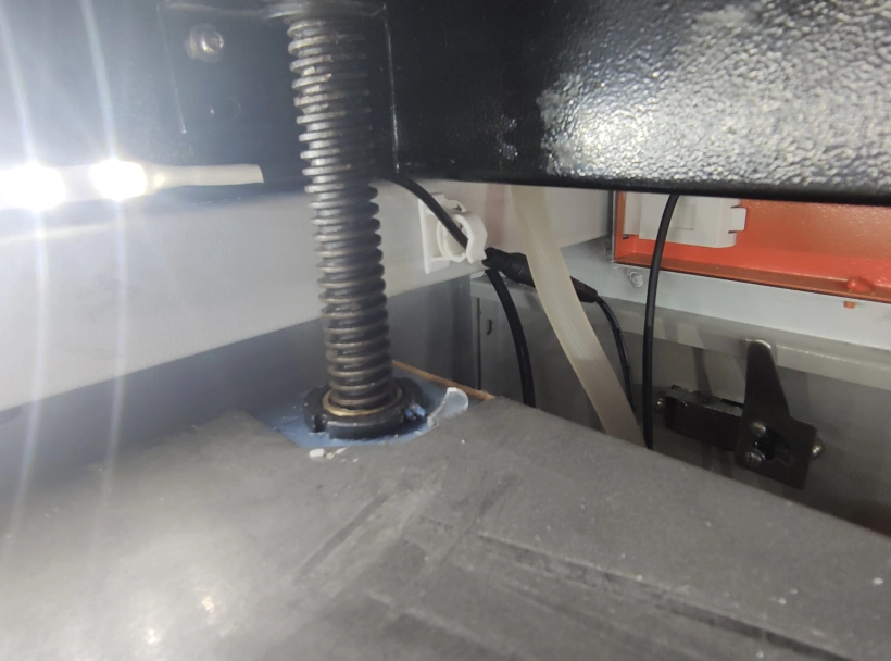
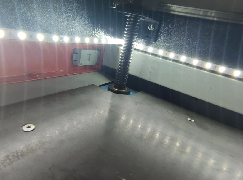
While checking out the Z-axis travel, I noticed that there was a wobble in the bed as it travelled up and down. The front right thread was a little loose, so I tightened it up to see if it would eliminate the wobble. Tightening the screw actually altered the squareness of the X & Y axis causing the Y-axis to grind when moving. Slackening off the screw was enough to return the machine to it’s previous smooth movement.
Fume Extraction for Your Laser Engraving and Cutting Machine
I am in the process of getting my fume extraction sorted, so at the moment it is as basic as putting the hose outside through a window. This is not ideal for a number of reasons:
- Fumes will slowly make their way back into the room and as the build up is slow, you may not actually notice the build-up.
- You are losing heat through the open window. Or allowing heat in, if you have an air conditioned room. Either way you are losing energy.
- On a wet day, you will be letting the elements in.
- The hose is highly visible and may generate questions from your neighbours.
As I am not going to be doing any high volume work, I am proposing to fit a tile vent with extraction port which will allow the fumes to be vented through the roof.
I will modify the extraction on my machine, so that will turn on as soon as the laser switch is activate. When modified, it will only turn on when a job is running and turn off 15 seconds after the job has finished. This will allow the air to clear and act as an indicator, not to open the lid until the fan has stopped and getting a face full of smoke.
How To Add Lights To A Chinese Laser.
The original supplied internal light did work, but could not be considered safe solution. It consisted of a number of LED’s connected to the mains voltage via a small circuit. There was also a pass through port for daisy chaining that had live pins easily accessible with your fingers.
This was certainly not something I would continue to use. So I decided I would put in my own, safe, LED lighting. I was planning to add a digital milliammeter and digital thermometer to my machine, that required a 12V supply. So, after a quick search on Amazon, I ordered a 5m, self adhesive strip of 12V LED’s.
I now needed a 12V supply to run everything. Luckily, I had an old Laptop 45W PSU which had an output of 19.5V and 2.3A. I then needed to regulate the supply to 12V so I purchased a cheap ZK-4KX Buck Boost that was more than adequate.
So I attached the 19.5V from the laptop PSU to the ZK-4KX and adjusted the output voltage to 12V. The LED’s were then fitted in a continuous strip from the top left hand corner, to the front of the machine, across the front and then to the back right hand corner.
I did it this way because I need to photograph and record jobs on the laser bed and I didn’t want to have lights glaring directly into the camera lens. It also means that the light is consistent when the lid is open or closed.


The CE Mark
With a prominent CE mark on both the packaging and the machine itself, it looks like this machine is safe to use. However, there is no way this machine complies with European Standards and should therefore be used for personal hobby use only. Don’t use this machine for business use where it will potentially be used by an employee. I will do another post describing the many ways the machine is not compliant.
Conclusion: Was it worth it?
At £1089 / $1400 it’s a mechanically sound laser cutting and engraving machine even though the wiring is a little suspect. I am not expecting the tube to be great and will probably change it and possibly the Laser PSU in the next 6 months, but I had factored in that cost at the beginning. A 50W laser tube from Cloudray Laser for example is likely to set me back £250 / $320 including delivery. An exact replacement for my MYJG-50 Laser PSU would Cost about £45 / $59.
I have a lot of upgrade plans for this machine which I will be posting as and when I complete the upgrades. Once I have finished with my upgrades, I should have a fast, accurate and reliable laser cutting and engraving machine that will be capable of processing most materials up to about 5~8mm in thickness.
What Next?
Did you enjoy this post? Why not check out some of our other posts:
Disclaimer
Last updated April 25, 2024
WEBSITE DISCLAIMER
The information provided by n-Deavor Limited, trading as Laseruser.com (“we,” “us” , or “our”) on (the “Site”) is for general informational purposes only. All information on the Site is provided in good faith, however we make no representation or warranty of any kind, express or implied, regarding the accuracy, adequacy, validity, reliability, availability or completeness of any information on the Site.
UNDER NO CIRCUMSTANCE SHALL WE HAVE ANY LIABILITY TO YOU FOR ANY LOSS OR DAMAGE OF ANY KIND INCURRED AS A RESULT OF THE USE OF THE SITE OR RELIANCE ON ANY INFORMATION PROVIDED ON THE SITE. YOUR USE OF THE SITE AND YOUR RELIANCE ON ANY INFORMATION ON THE SITE IS SOLELY AT YOUR OWN RISK.
EXTERNAL LINKS DISCLAIMER
The Site may contain (or you may be sent through the Site) links to other websites or content belonging to or originating from third parties or links to websites and features in banners or other advertising. Such external links are not investigated, monitored, or checked for accuracy, adequacy, validity, reliability, availability or completeness by us.
WE DO NOT WARRANT, ENDORSE, GUARANTEE, OR ASSUME RESPONSIBILITY FOR THE ACCURACY OR RELIABILITY OF ANY INFORMATION OFFERED BY THIRD-PARTY WEBSITES LINKED THROUGH THE SITE OR ANY WEBSITE OR FEATURE LINKED IN ANY BANNER OR OTHER ADVERTISING.
WE WILL NOT BE A PARTY TO OR IN ANY WAY BE RESPONSIBLE FOR MONITORING ANY TRANSACTION BETWEEN YOU AND THIRD-PARTY PROVIDERS OF PRODUCTS OR SERVICES.
AFFILIATES DISCLAIMER
The Site may contain links to affiliate websites, and we receive an affiliate commission for any purchases made by you on the affiliate website using such links. Our affiliates include the following:
- makeCNC who provide Downloadable Patterns, Software, Hardware and other content for Laser Cutters, CNC Routers, Plasma, WaterJets, CNC Milling Machines, and other Robotic Tools. They also provide Pattern Files in PDF format for Scroll Saw Users. They are known for their Friendly and Efficient Customer Service and have a comprehensive back catalogue as well as continually providing New Patterns and Content.
- Cloudray Laser: a world-leading laser parts and solutions provider, has established a whole series of laser product lines, range from CO2 engraving & cutting machine parts, fiber cutting machine parts and laser marking machine parts.
